164 www.xilinx.com Virtex-6 FPGA GTX Transceivers User Guide
UG366 (v2.5) January 17, 2011
Chapter 3: Transmitter
Ports and Attributes
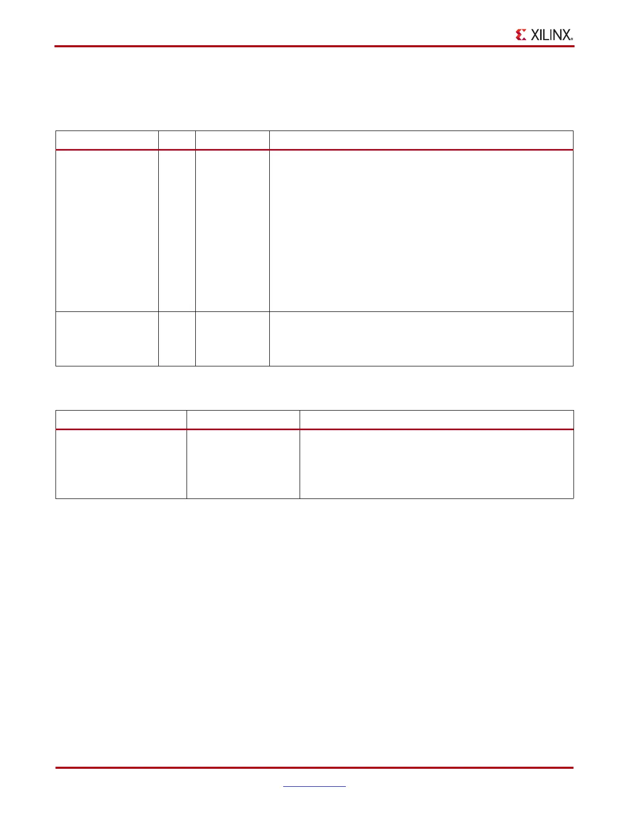
Table 3-24 defines the pattern generator ports.
Table 3-25 defines the pattern generator attribute.
Use Models
The pattern generation and check function are usually used for verifying link quality test
and also for jitter tolerance test. For link quality testing, choose test pattern by setting
TXENPRBSTST and RXENPRBSTST to non-000, and set RXPRBSERR_LOOPBACK to 0
(Figure 3-26). Only the PRBS pattern is recognized by the RX pattern checker.
Table 3-24: Pattern Generator Ports
Port Dir Clock Domain Description
TXENPRBSTST[2:0] In TXUSRCLK2 Transmitter PRBS generator test pattern control.
000: Standard operation mode (test pattern generation is OFF)
001: PRBS-7
010: PRBS-15
011: PRBS-23
100: PRBS-31
101: PCI Express compliance pattern. Only works with 20-bit
mode
110: Square wave with 2 UI (alternating 0’s/1’s)
111: Square wave with 16 UI or 20 UI period (based on data
width)
TXPRBSFORCEERR In TXUSRCLK2 When this port is driven High, errors are forced in the PRBS
transmitter. While this port is asserted, the output data pattern
contains errors. When TXENPRBSTST is set to 000, this does not
affect TXDATA.
Table 3-25: Pattern Generator Attribute
Attribute Type Description
RXPRBSERR_LOOPBACK 1-bit Binary When set to 1, causes RXPRBSERR bit to be internally looped
back to TXPRBSFORCEERR of the same GTX transceiver. This
allows synchronous and asynchronous jitter tolerance testing
without worrying about data clock domain crossing.
When set to 0, TXPRBSFORCEERR forces onto the TX PRBS.

 Loading...

