168 www.xilinx.com Virtex-6 FPGA GTX Transceivers User Guide
UG366 (v2.5) January 17, 2011
Chapter 3: Transmitter
5. The selection of the /4 or /5 divider block is dependent on TX_DATA_WIDTH (see
Table 3-1, page 128):
• /4 is selected when the internal data width is 16
• /5 is selected when the internal data width is 20
For details about placement constraints and restrictions on clocking resources (MMCM,
BUFGCTRL, IBUFDS_GTXE1, BUFG, etc.), refer to the Virtex-6 FPGA Clocking Resources
User Guide.
Serial Clock Divider
Each transmitter PMA module has a D divider that divides down the clock from the PLL
for lower line rate support. This divider can be set statically for applications with a fixed
line rate or it can be changed dynamically for protocols with multiple line rates.
To use the D divider in fixed line rate applications, the TXPLL_DIVSEL_OUT attribute
must be set to the appropriate value, and the TXRATE port needs to be tied to 00.
To use the D divider in multiple line rate applications, the TXRATE port is used to
dynamically select the D divider value. The TXPLL_DIVSEL_OUT attribute and the
TXRATE port must select the same D divider value upon device configuration. After
device configuration, the TXRATE is used to dynamically change the D divider value.
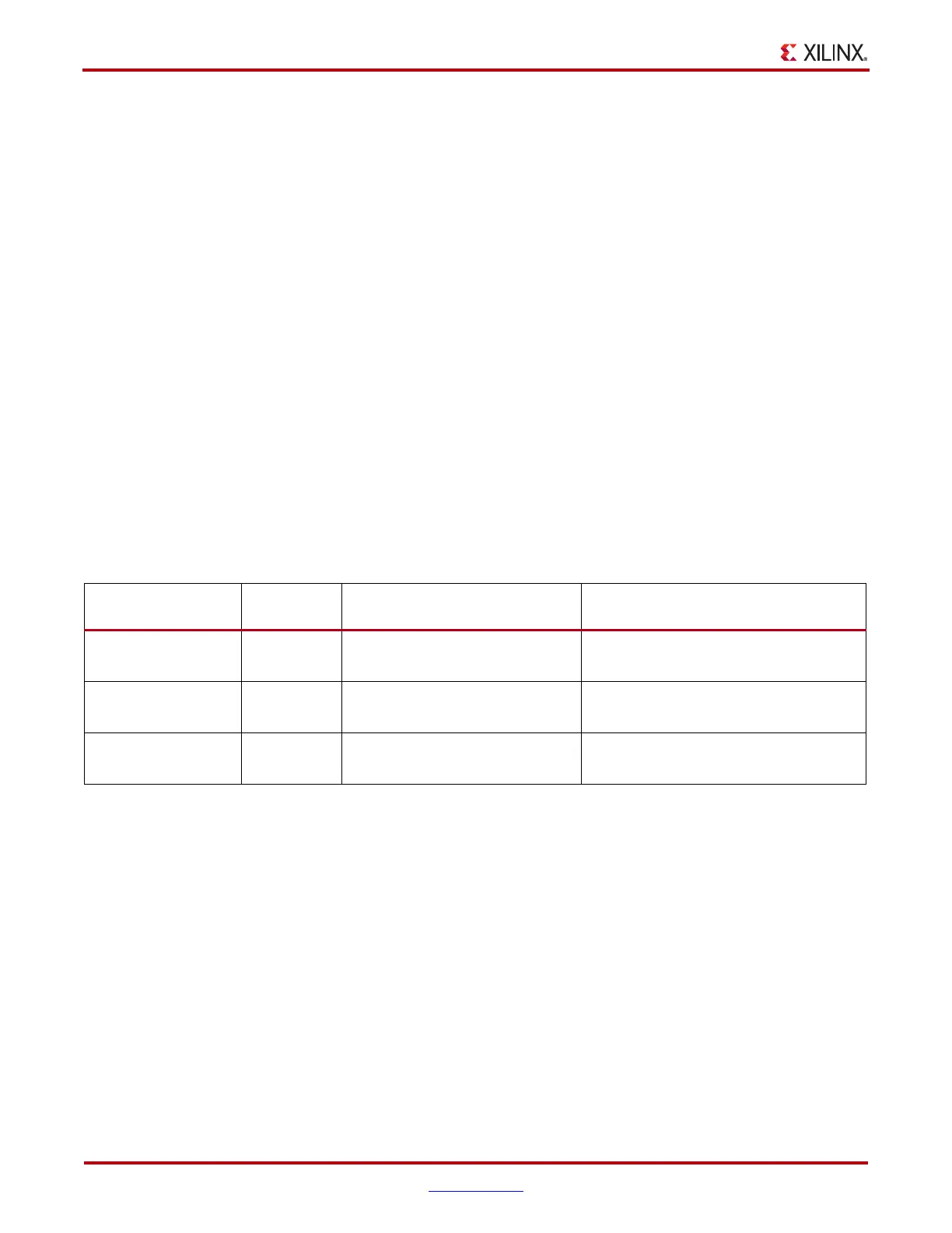
The control for the serial divider is described in Table 3-28. For details about the line rate
range per speed grade, refer to the Virtex-6 FPGA Data Sheet.
Parallel Clock Divider and Selector
The parallel clock outputs from the TX Fabric Clock Output Control block can be used as a
fabric logic clock. The parallel clock divider block can output a 1-byte or 2-byte data width
clock.
The recommended clock for the fabric is the TXOUTCLK from one of the GTX transceivers.
It is also possible to bring the MGTREFCLK directly to the fabric and use as the fabric
clock. TXOUTCLK is preferred for general applications as it has an output delay control
used for applications that bypass the TX buffer for output lane deskewing or constant
datapath delay. Refer to TX Buffer Bypass, page 155 for more details.
The TXOUTCLK_CTRL attribute controls the input selector and allows the following
clocks to be output via TXOUTCLK port:
• TXOUTCLKPCS: This clock should only be used when the TX Oversampling block is
enabled. The TX Oversampling block divides down the TXOUTCLKPMA_DIV2 clock
to match the 5X oversampled data rate.
Table 3-28: TX PLL Output Divider Setting
Line Rate Range
(Gb/s)
D Divider
Value
Static Setting via Attribute Dynamic Control via Ports
2.40 to 6.60 1
TXPLL_DIVSEL_OUT = 1
TXRATE = 00
TXRATE = 11
1.20 to 3.3 2
TXPLL_DIVSEL_OUT = 2
TXRATE = 00
TXRATE = 10
0.60 to 1.65 4
TXPLL_DIVSEL_OUT = 4
TXRATE = 00
TXRATE = 01

 Loading...

