124 www.xilinx.com Virtex-6 FPGA GTX Transceivers User Guide
UG366 (v2.5) January 17, 2011
Chapter 2: Shared Transceiver Features
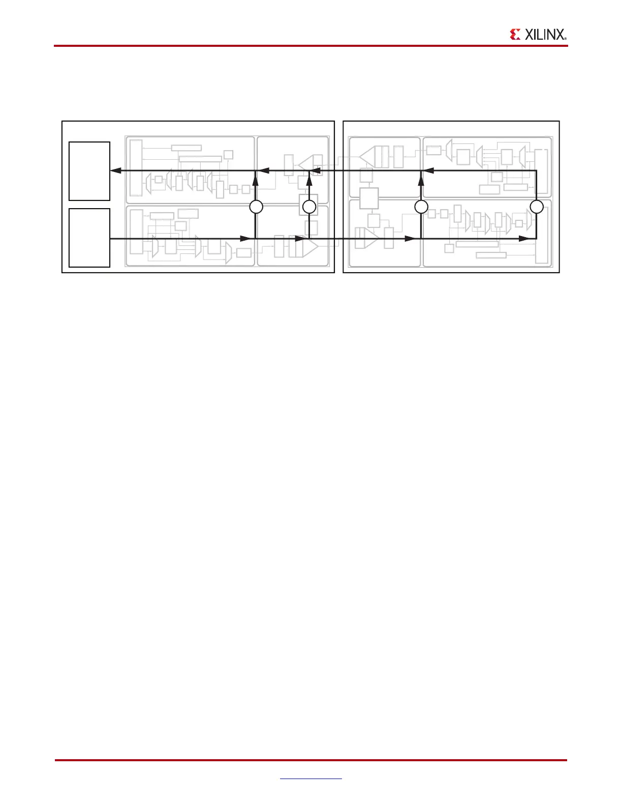
and then compared to check for errors. Figure 2-10 illustrates a loopback test configuration
with four different loopback modes.
Loopback test modes fall into two broad categories:
• Near-end loopback modes loop transmit data back in the transceiver closest to the
traffic generator.
• Far-end loopback modes loop received data back in the transceiver at the far end of
the link.
Loopback testing can be used either during development or in deployed equipment for
fault isolation. The traffic patterns used can be either application traffic patterns or
specialized pseudo-random bit sequences. Each GTX transceiver has a built-in PRBS
generator and checker.
Each GTX transceiver features several loopback modes to facilitate testing:
• Near-End PCS Loopback (path 1 in Figure 2-10)
• Near-End PMA Loopback (path 2 in Figure 2-10)
• Far-End PMA Loopback (path 3 in Figure 2-10)
• Far-End PCS Loopback (path 4 in Figure 2-10)
Ports and Attributes
Table 2-16 defines the loopback ports.
X-Ref Target - Figure 2-10
Figure 2-10: Loopback Testing Overview
X-PM
X-P
X-PM
X-PC
-
X-P
-
TX-PC
Near-End GTX
Link Near-End Test Structures Link Far-End Test Structures
Test Logic
UG366_c2_07_081109
Far-End GTX
Traffic
Checker
Traffic
Generator
1 432

 Loading...

