220 www.xilinx.com Virtex-6 FPGA GTX Transceivers User Guide
UG366 (v2.5) January 17, 2011
Chapter 4: Receiver
Alignment Boundaries
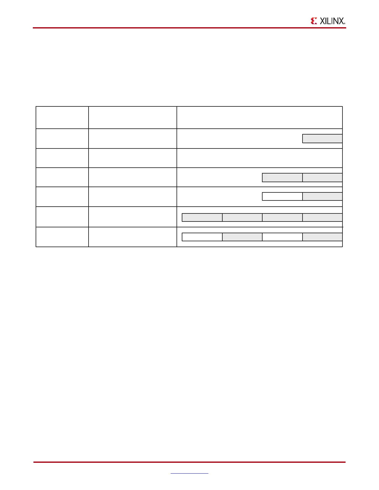
The allowed boundaries for alignment are defined by ALIGN_COMMA_WORD. The
spacing of the possible boundaries is determined by RX_DATA_WIDTH, and the number
of boundary positions is determined by the number of bytes in the RXDATA interface
(refer to Table 4-56, page 269 for RX_DATA_WIDTH settings). Figure 4-21 shows the
boundaries that can be selected.
Manual Alignment
RXSLIDE can be used to override the automatic comma alignment and shift the parallel
data. RXSLIDE is driven High for one RXUSRCLK2 cycle to shift the parallel data by one
bit. RXSLIDE must be Low for at least 16 RXUSRCLK2 cycles before it can be used again.
Figure 4-27 shows the waveforms for manual alignment using RXSLIDE in
RX_SLIDE_MODE = PCS before and after the data shift.
X-Ref Target - Figure 4-26
Figure 4-26: Comma Alignment Boundaries
RX_DATA_WIDTH
8/10
(1-byte)
8/10
(1-byte)
16/20
(2-byte)
16/20
(2-byte)
ALIGN_COMMA_WORD
1 (Any Boundary)
2 (Even Boundaries Only)
1 (Any Boundary)
UG366_c4_24_102910
2 (Even Boundaries Only)
Possible RX Alignments
(Grey = Comma Can Appear on Byte)
RXDATA Byte 0
Invalid Configuration
RXDATA Byte 1 RXDATA Byte 0
RXDATA Byte 1 RXDATA Byte 0
32/40
(4-byte)
1 (Any Boundariy)
RXDATA Byte 1
RXDATA Byte 0
RXDATA Byte 0
RXDATA Byte 0
RXDATA Byte 3
RXDATA Byte 2
RXDATA Byte 1 RXDATA Byte 0
RXDATA Byte 0
RXDATA Byte 3
RXDATA Byte 2
32/40
(4-byte)
2 (Even Boundaries Only)

 Loading...

