Virtex-6 FPGA GTX Transceivers User Guide www.xilinx.com 255
UG366 (v2.5) January 17, 2011
RX Channel Bonding
CHAN_BOND_1_MAX_SKEW and CHAN_BOND_2_MAX_SKEW are used to set the
maximum skew allowed for channel bonding sequences 1 and 2, respectively. The
maximum skew range is 1 to 14. This range must always be less than one-half the
minimum distance (in bytes or 10-bit codes) between channel bonding sequences. This
minimum distance is determined by the protocol being used.
Precedence between Channel Bonding and Clock Correction
The clock correction (see RX Clock Correction, page 240) and channel bonding circuits
both perform operations on the pointers of the RX elastic buffer. Normally, the two circuits
work together without conflict, except when clock correction events and channel bonding
events occur simultaneously. In this case, one of the two circuits must take precedence. To
make clock correction a higher priority than channel bonding, CLK_COR_PRECEDENCE
must be set to TRUE. To make channel bonding a higher priority,
CLK_COR_PRECEDENCE must be set to FALSE.
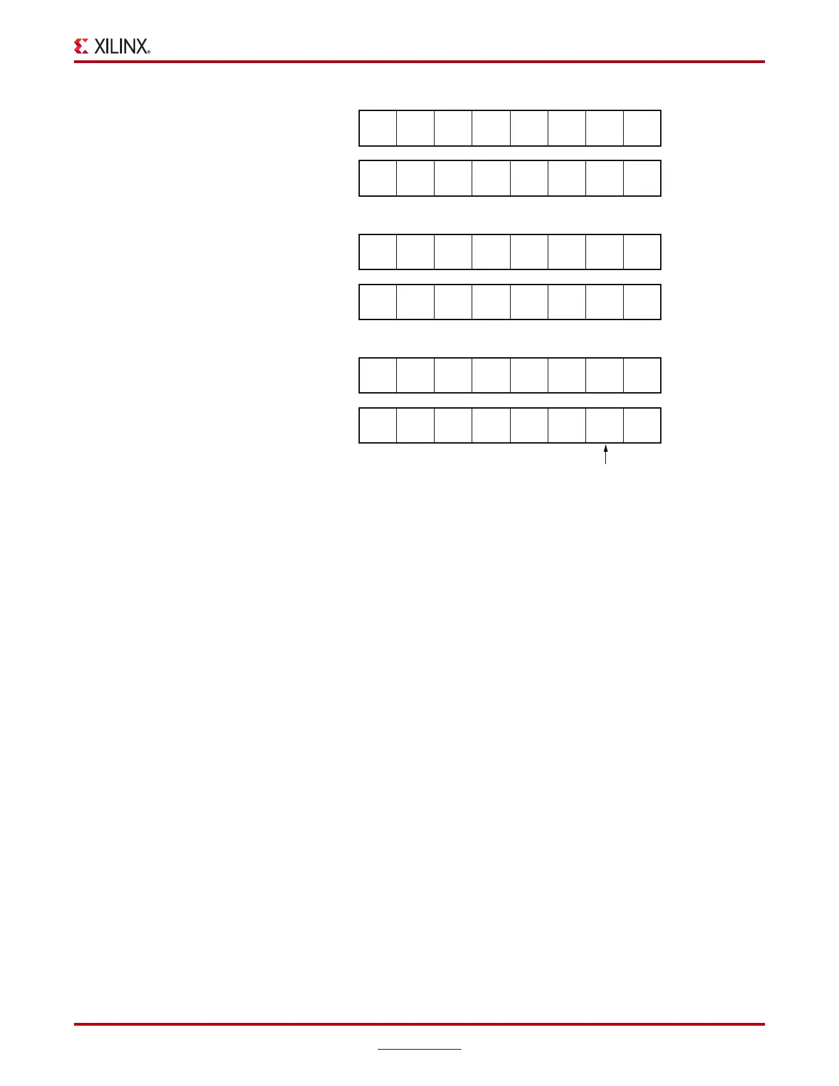
X-Ref Target - Figure 4-44
Figure 4-44: Channel Bonding Example (CHAN_BOND_*_MAX_SKEW = 2 and Master
RXCHANBONDLEVEL[2:0] = 1)
The Master waits MAX SKEW cycles before
triggering bonding, giving the slave time to
receive the sequence as well. The message
to perform channel bonding is sent using
the CHBONDO port.
The CHAN_BOND_LEVEL setting of the Master
determines how many cycles later the bonding
operation is executed. At this time, the Slave
Elastic Buffer pointers are moved so the
output is deskewed.
Master
Receives CB
Sequence
Master
Elastic
Buff
er
Slave
Elastic
Buffer
Master
Elastic
Buffer
Slave
Elastic
Buffer
Master
Elastic
Buffer
Slave
Elastic
Buffer
UG366_c4_41_051509
Slave’s New Elastic
Buffer Read Pointer
D1D2D3D4D5D6D7SEQ1
D1D2D3D4D5D6D7 D0
D4D5D6D7SEQ1D8D9D10
D4D5D6D7SEQ1D8D9 D3
D5D6D7SEQ1D8D9D10D11
D5D6D7SEQ1D8D9D10 D4

 Loading...

