Virtex-6 FPGA GTX Transceivers User Guide www.xilinx.com 179
UG366 (v2.5) January 17, 2011
TX Receiver Detect Support for PCI Express Designs
TX Receiver Detect Support for PCI Express Designs
Functional Description
The PCI Express specification includes a feature that allows the transmitter on a given link
to detect if a receiver is present. The decision if a receiver is present is based on the rise time
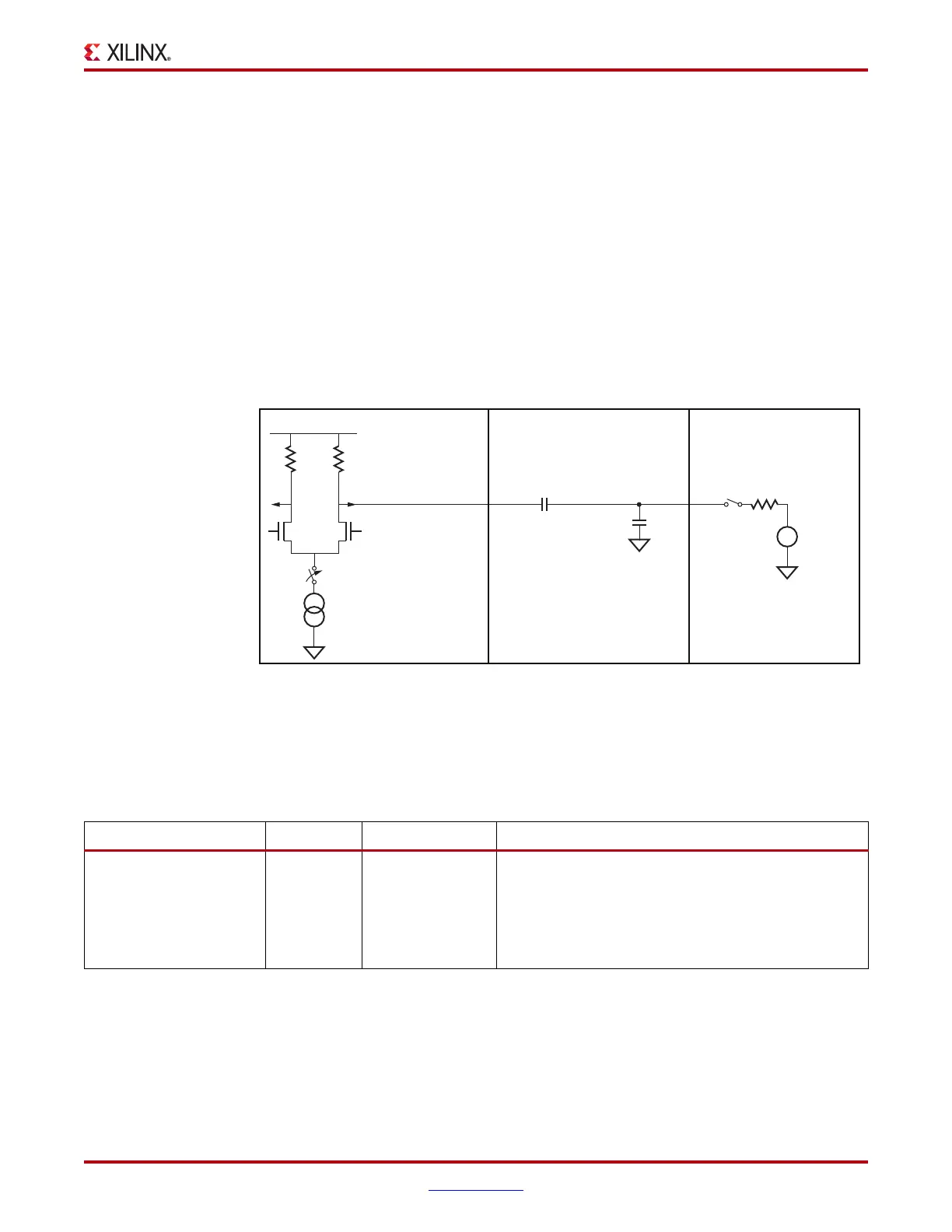
of TXP/TXN. Figure 3-32 shows the circuit model used for receive detection. The GTX
transceiver must be in the P1 power-down state to perform receiver detection. Also
receiver detection requires a 75 to 200 nF external coupling capacitor between the
transmitter and receiver, and the receiver must be terminated to GND. The detection
sequence starts with the assertion of TXDETECTRX. In response, the Receiver Detect logic
drives TXN and TXP to V
DD
–V
SWING
/2 and then releases them. After a programmable
interval, the levels of TXN and TXP are compared with a threshold voltage. At the end of
the sequence, RXSTATUS and PHYSTATUS reflect the results of the receiver detection.
Ports and Attributes
Table 3-33 defines the TX receiver detect support ports.
X-Ref Target - Figure 3-32
Figure 3-32: Receiver Detection Circuit Model
C
CH
: < 3 nF
UG366_c3_20_051509
C
AC
: 75 nF - 200 nF
R
TERMR
: 40Ω - 60Ω
V
TERMR
R
TERMT
: 40Ω - 60Ω
V
DD
TXDETECTRX
GTX Transceiver
Components
Channel
Components
Far-End Receiver
Components
TXP
Table 3-33: TX Receiver Detect Support Ports
Port Dir Clock Domain Description
PHYSTATUS Out RXUSRCLK2/
Async
This signal is asserted High to indicate completion of
several PHY functions, including power management
state transitions and receiver detection. When this
signal transitions during entry and exit from P2 and
RXUSRCLK2 is not running, the signaling is
asynchronous.

 Loading...

