Virtex-6 FPGA GTX Transceivers User Guide www.xilinx.com 191
UG366 (v2.5) January 17, 2011
RX Analog Front End
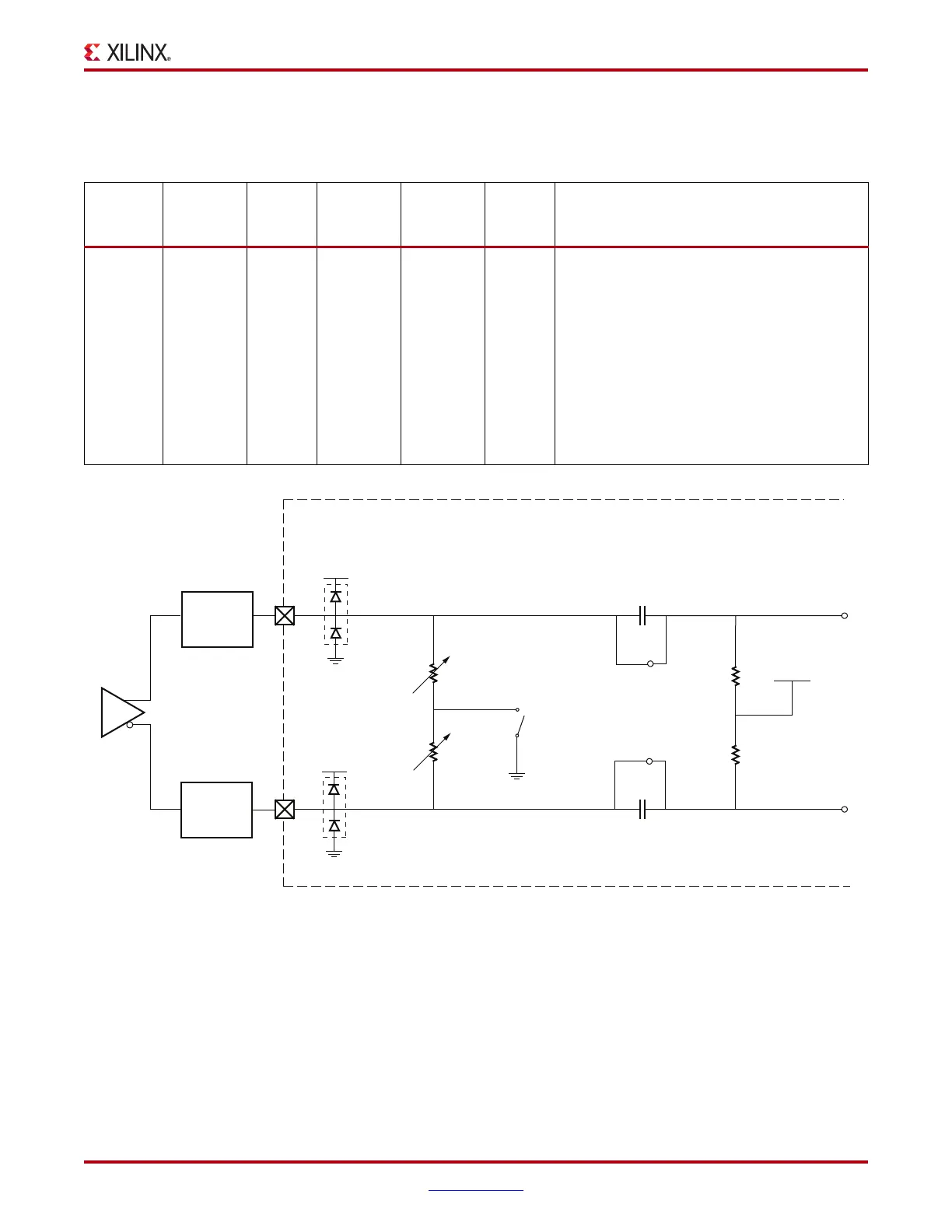
Table 4-8 outlines the recommended settings for RX termination in Use Mode 5. Figure 4-7
shows the Use Mode 5 configuration.
Use Mode – Resistor Calibration
For more information on the on-chip resistor calibration, refer to Termination Resistor
Calibration Circuit, page 274.
Table 4-8: RX Termination Use Mode 5 Configuration and Notes
Use Mode
External
AC
Coupling
Term
Voltage
Internal AC
Coupling
Internal
Bias
Max
Swing
mV
DPP
Suggested Protocols and Usage Notes
5 OFF Float/
GND
OFF 800 mV 1600 Protocol: GPON
Attribute Settings:
AC_CAP_DIS = TRUE
RCV_TERM_GND = TRUE / FALSE
RCV_TERM_VTTRX = FALSE
Notes:
True DC mode. A DC common mode of 2/3
MGTAVTT_* (800 mV) is required. To achieve
this, an external level shifting network might
be required.
X-Ref Target - Figure 4-7
Figure 4-7: RX Termination Use Mode 5 Configuration
UG366_c4_07_071009
nominal
50Ω
nominal
50Ω
FPGABoard
MGTAVTT_*
MGTAVTT_*
nominal 7 pFESD Diodes
ESD Diodes nominal 7 pF
nominal
50 KΩ
nominal
50 KΩ
V
CM
2/3 MGTAVTT_*
External
Te r mi nation
Network
External
Te r mi nation
Network
GND

 Loading...

