Virtex-6 FPGA GTX Transceivers User Guide www.xilinx.com 277
UG366 (v2.5) January 17, 2011
Pin Description and Design Guidelines
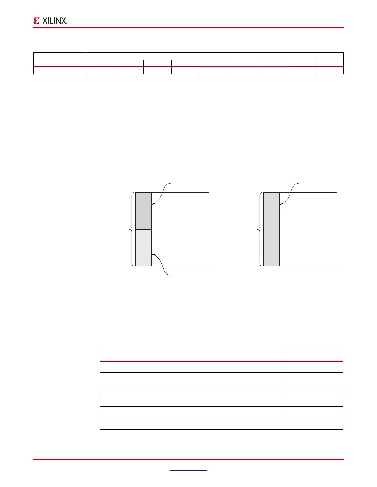
Figure 5-4 shows the orientation in the device of the Quad power banks within a device.
The type of grouping for the Quads in a column depends on the device package. The FF484
and FF784 packages have a single common power plane for each of the GTX transceiver
supplies. The FF1156 and FF1759 packages have two power planes for each of the GTX
transceiver power supplies.
Unused Quad Column
If none of the Quads in a column are used in the application, the Quad device pins can be
connected as shown in Table 5-3.
XC6VSX475T-FF1759 South South South South South North North North North
Notes:
1. Each Quad contains four transceivers.
2. FF484 and FF784 packages only have one common internal power plane for each of the Quad analog power supplies.
3. Common: The Quad is powered by a common set of power planes (MGTAVCC, MGTAVTT).
4. South: The Quad is powered by South package power planes (MGTAVCC_S, MGTAVTT_S).
5. North: The Quad is powered by North package power planes (MGTAVCC_N, MGTAVTT_N).
6. North and South represent the two planes for each of the analog power supplies, MGTAVCC and MGTAVTT.
Table 5-2: Connected Quads (Cont’d)
Device
Quad
(1)
MGT110 MGT111 MGT112 MGT113 MGT114 MGT115 MGT116 MGT117 MGT118
X-Ref Target - Figure 5-4
Figure 5-4: GTX Power Plane Bank Orientation in Virtex-6 FPGA Packages
N
O
R
T
H
S
O
U
T
H
Virtex-6
FPGA
Packages:
FF1156, FF1759
MGTAVCC_N
MGTAVTT_N
MGTAVCC_S
MGTAVTT_S
Tranceiver
Column
C
O
M
M
O
N
Virtex-6
FPGA
Packages:
FF784, FF484
MGTAVCC
MGTAVTT
Tranceiver
Column
UG366_c5_04_051509
Table 5-3: Unused Quad Column Connections
Quad Pin or Pin Pair of the Unused Column Connection
MGTAVCC GND
MGTAVTT GND
MGTREFCLKP/MGTREFCLKN FLOAT
MGTRXP/MGTRXN GND
MGTTXP/MGTTXN FLOAT
MGTAVTTRCAL
(1)
GND

 Loading...

