8–10 Altera Corporation
Stratix Device Handbook, Volume 2 July 2005
Interfaces
With this XSBI transmitter and receiver block implementation, each XSBI
core requires two fast PLLs. The potential number of XSBI cores per
device corresponds to the number of fast PLLs each Stratix or Stratix GX
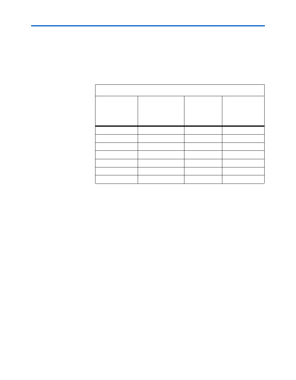
device contains. Tables 8–2 and 8–3 show the number of LVDS channels,
the number of fast PLLs, and the number of XSBI cores that can be
supported for each Stratix or Stratix GX device.
Table 8–2. Stratix Device XSBI Core Support
Stratix Device
Number of LVDS
Channels
(Receive/Transmit)
(1)
Number of Fast
PLLs
Number of XSBI
Interfaces
(Maximum)
EP1S10 44/44 4 2
EP1S20 66/66 4 2
EP1S25 78/78 4 2
EP1S30 82/82 8 4
EP1S40 90/90 8 4
EP1S60 116/116 8 4
EP1S80 152/156 8 4
Note to Ta b le 8 – 2 :
(1) The LVDS channels can go up to 840 Mbps for flip-chip packages and up to
624 Mbps for wire-bond packages. This number includes both high speed and
low speed channels. The high speed LVDS channels can go up to 840 Mbps. The
low speed LVDS channels can go up to 462 Mbps. The High-Speed Differential I/O
Support chapter in the Stratix Device Handbook, Volume 1, and the device pin-outs
on the web (www.altera.com) specify which channels are high and low speed.