4. TSM Service Program 1/2010 4 - 43
BA-TE-DE08C M.KAY Dialog+ SW9xx_SM_Chapter 4-1-1_1-2010.doc/pdf <110301> yymmdd B. Braun Avitum AG
Dialog
+
SW 9.xx
Central Automatic Chemical Disinfection
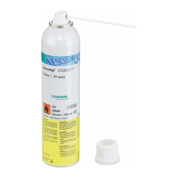
The hypochlorite disinfectant Tiutol KF must be applied (mixing ratio
maximum 65 ml Tiutol KF per litre).
The user is responsible to integrate the dialysis machine in the dialysis
centre’s central water loop system, if the
Central Automatic Chemical
Disinfection
is used.
The retention time must be ≤ 10 hours if the retention is disabled, i.e. the
Retention Time
is set to
YES
, thus, no
Central Automatic Chemical
Disinfection
.
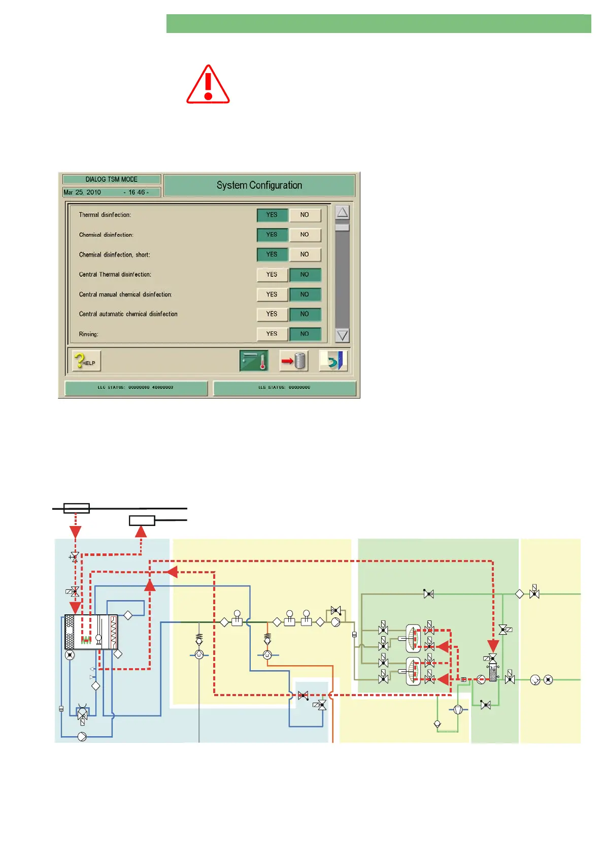
This disinfection method can be used for the
disinfection of the water inlet line in dialysis
centres with central water loop systems.
A defined inlet volume (disinfectant) from the
water loop line is sucked in as follows (see dotted
lines in the flow diagram):
• FPA/UFP decrease the water level in the
upline tank VB to the lower level sensor
NSVB
• The upline tank VB (approx. 260 ml inlet
volume) is filled with disinfectant to the
upper level sensor NSVB, due to the water
pressure at VVBE from
• the central water loop system
• Filling is repeated until the preselected
volume is reached
• Retention time (machine is switched off)
• Rinsing via VB, RVE, VLA, LA and FPA to the
outlet
Phase 1
• machine is filled and emptied 5 times, i.e the disinfectant is volume
controlled and sucked in and emptied by the central water loop line
Phase 2
• cyclic rinsing (time controlled -- rinsing time and rinsing flow
EK
RVUFP
CD
VBP
B
C
FBK2
FBK1
RVFPA
LAFS
RVDA
VZ
VLA
VDA
VABK2
VDABK2
VABK1
VDABK1
BK2
BK1
VEBK2
VDEBK2
VEBK1
VDEBK1
MS B K2
MS B K1
LA
UFP
ENDLF-SENDLF
BICLFTSBIC
TSD
RVFPE
BL
FPE
PDA
FPA
TSD-S
DMV
VVBE
TSE
H
NSVB
TSHE
T
8
T
A
D
T
8
VB
WT
FEP
T
DDE VDE
SDE
WA B
Central Water Loop System
Outlet
EP
VEB
PE TSH
T
8
RVK
RVB
A
B
BICP
KP
Fig.: Flow Diagram - Central Automatic Chemical Disinfection of Water Inlet