1 689 989 067 2017-12-08| Robert Bosch GmbH
Maintenance | EPS 708 | 59 en
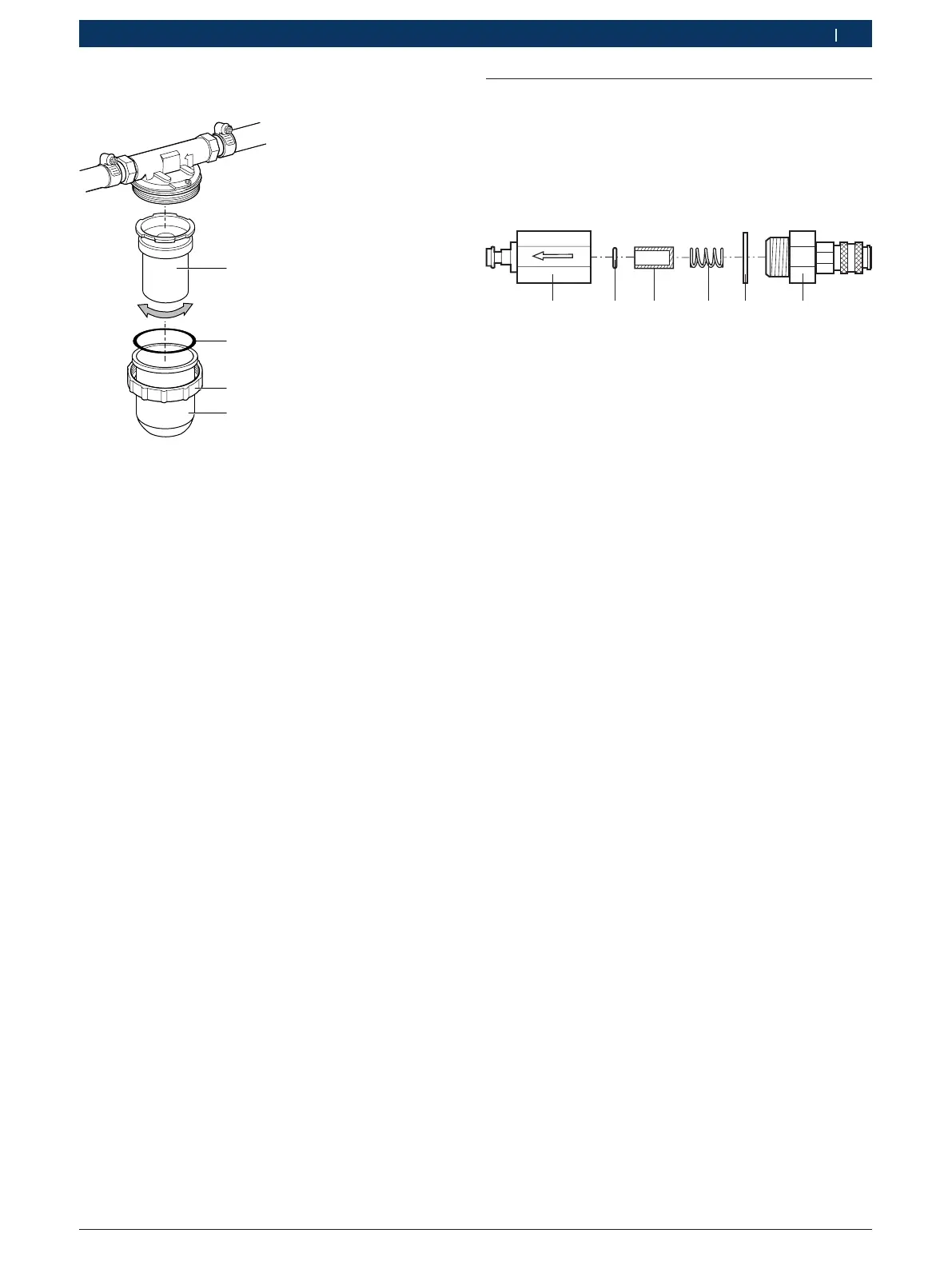
6.8.2 Replacing the flow meter filter element
1
2
3
4
458846-16_Ko
Fig. 24: Flow meter filter
1 Filter element
2 O-ring
3 Union nut
4 Filter housing
1. Unscrew union nut (fig. 24, item 3) and remove it
along with filter housing (fig. 24, item 4).
2. Remove O-ring (fig. 24, item 2).
3. Detach filter element (fig. 24, item 1) clockwise and
remove it.
4. Dispose of O-ring (fig. 24, item 2) and filter element
(fig. 24, item 1).
5. Insert new filter element and tighten it
counterclockwise.
i Make sure the sealing surfaces and the O-ring are
clean during installation.
6. Attach filter housing with new O-ring. Hand-tighten
union nut. Do not use force.
" The filter element has been replaced.
6.8.3 Changing the pump return filter element
¶ For filter change, see section 6.8.2.
6.9 Replacing the inlet filter cartridge
(e.g. Injector A)
i The sediments in the inlet filters are mainly
attributable to not or insufficiently cleaned common
rail injectors before testing.
Fig. 25: Replacing the filter cartridge
1 Threaded joint
2 Flat seal
3 Spring
4 Filter cartridge
5 O-ring
6 Threaded joint
1. Detach the inlet filter from the quick-release
couplings.
2. Using two wrenches, slacken and completely
unscrew the threaded joints (fig.25, pos. 1 and 6).
3. Take out the flat seal, spring, filter cartridge and
O-ring (fig. 25, pos. 2, 3, 4, 5).
4. Remove and dispose of the flat seal, filter cartridge
and O-ring.
5. Clean both threaded joints with clean calibrating oil.
6. Insert a new O-ring.
7. Insert a new filter cartridge, ensuring the correct
position.
8. Put on a new flat seal.
9. Insert the spring.
10. Screw the threaded joints together and tighten with
the torque wrench (tightening torque = 50Nm).
" The filter cartridge is now changed.
! The inlet filters must always be inserted in the
injected fuel quantity inlets A to F (fig. 2, pos. 8)
(note the direction of flow of the inlet filters).
Never insert them in the injection chambers!