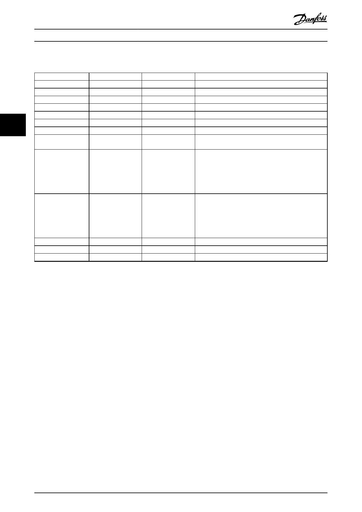
4.5.2 SAB-specic LCP Parameters
Parameter number Name Unit Description
00-20 Display line 1.1 small – Select a variable for display in line 1, left position.
00-21 Display line 1.2 small – Select a variable for display in line 1, middle position.
00-22 Display line 1.3 small – Select a variable for display in line 1, right position.
00-23 Display line 2 large – Select a variable for display in line 2.
00-24 Display line 3 large – Select a variable for display in line 3.
50-17 U
AUX
Control – Enables or disables AUX line voltage.
50-18 UDC Control – Enables or disables UDC.
50-81 Position guide value
reference
Degrees (°) Scaled position guide value reference (0–360°).
51-64 AUX line 1 user limit A Sets a user limit for the current on auxiliary line 1. The
current limit can be set in steps of 0.1 A. The value 0 disables
the user current limitation. A warning is set when 90% of the
user current limit is exceeded. Once 100% of the user current
limit is exceeded, the line is switched o and the SAB enters
an error state.
51-65 AUX line 2 user limit A Sets a user limit for the current on auxiliary line 2. The
current limit can be set in steps of 0.1 A. The value 0 disables
the user current limitation. A warning is set when 90% of the
user current limit is exceeded. Once 100% of the user current
limit is exceeded, the line is switched o and the SAB enters
an error state.
54-10 Epl id assignment line – Selects the SAB line number for the ID assignment.
54-11 Drive index – Selects the index of the device in the selected line (1–32).
54-13 Epl id assignment start – Starts the manual ID assignment.
Table 4.12 SAB-specic LCP Parameters
Local Control Panel (LCP) O...
VLT
®
Integrated Servo Drive ISD
®
510 System
108 Danfoss A/S © 01/2017 All rights reserved. MG36D102
44

 Loading...


