Callout Description Function
8 Vertical
scale
Both an input and a visualization control
for the units per vertical division, that is,
the vertical scale of the signal. The scale
value is shown in the same way as the
values at the left and right cursors: with 6
decimal places and in the unit shown by
Signal unit.
The vertical scale can be modied in 3
ways:
•
Type in the desired scale (units per
vertical division) in the eld.
•
Use the up/down arrows on the right
of the Vertical scale and Signal unit
elds.
•
Auto-scale the trace using the Auto
scale button (modies the vertical
scaling and the oset of this channel).
The up/down arrows for controlling the
vertical scale always change the scale
factor by 2: clicking on the up arrow does
a “vertical zoom-in”, meaning that the
Vertical scale is divided by 2; likewise,
clicking on the down arrow does a
“vertical zoom-out” and multiplies the
Vertical scale by 2.
9 Value at left
cursor
The left and right cursor elds show the
values of the trace data at the 2 cursors in
the unit shown by Signal unit. The 2 elds
are updated dynamically while dragging.
The value elds show the traced values to
6 decimal places.
Callout Description Function
10 Channel
display type
3-state button that alters the graph visual-
ization of the traced signals. The 3
possible states are:
•
Linear interpolation
•
Digital interpolation
•
Hidden line
In linear interpolation mode, each 2
subsequent samples are connected by a
straight line. This visualizes the traced
data as a continuous signal.
In digital interpolation mode, the traced
data is visualized as a discrete signal: the
value of the signal is instantly changed at
each sample and remains the same until
the next sample.
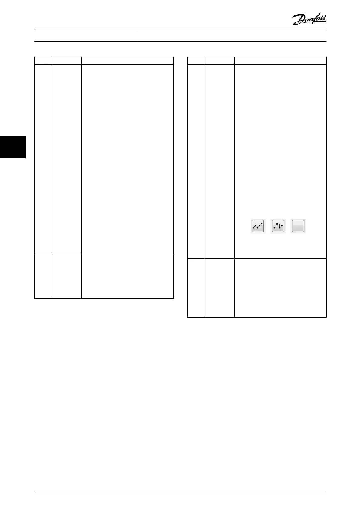
In hidden line mode, the traced data for
the channel is not visualized, although the
data is available. The icon of the channel
display type button changes according to
the current display type.
Visualization Icons: Linear Interpolation
(Left), Digital Interpolation (Middle), and
Hide (Right)
11 Signal name The drop-down list contains all available
signals on the device and selects the
signal to be traced on the given channel.
The signals are shown in alphabetical
order of their short names. When opening
the drop-down list and moving the mouse
cursor over a signal, the full name of the
signal is shown in a tooltip.
Table 5.9 Legend to Illustration 5.31
5.7.3.4 Status
The Scope sub-tool has 5 states:
•
Oine: Scope is running in oine mode. A trace
cannot be initiated.
•
Ready: Trace is not currently running and can be
started.
•
Waiting: A trace has been initiated and the Scope
is waiting for a status update from the device.
•
Acquiring: The device has started tracing data.
•
Triggered: Triggering is enabled and the trigger
point for the trace was reached.
5.7.3.5 Running a Trace
The Scope must be in state Ready in order to run a trace.
Click on the Run button shown in Illustration 5.33.
Operation with ISD Toolbox
VLT
®
Integrated Servo Drive ISD
®
510 System
128 Danfoss A/S © 01/2017 All rights reserved. MG36D102
55

 Loading...


