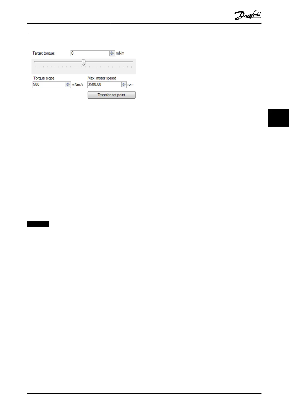
Illustration 5.44 Drive Control - Torque Prole Mode
The minimum and maximum values of both the Target
torque numeric eld and the Target torque slider are set to
match the Application torque limit parameter on the servo
drive, which is congurable in the eld for Additional
Parameters. The initial slider position is in the middle of the
slider, representing 0.
The mode of operation of the servo drive is set to Prole
Torque mode once the button Transfer set-point is clicked
or the Target torque slider is moved.
The parameters Torque slope and Max. motor speed are
needed to operate the servo drive in Torque Prole mode.
They are represented by the 2 respective numeric up/down
elds in the Torque Mode control. The Torque slope eld
shows its parameter value as mNm/s, and the Max. motor
speed eld is shown in the velocity unit set in the Options
window (see chapter 5.5.8 Options Window).
NOTICE
The Torque Prole mode control relies on cyclic
communication to send any commands to the servo
drive.
DS402 State Machine control
The DS402 State Machine control visualizes and controls the
servo drive state machine and can be used to enable or
disable the servo drive, and to reset an error. The control
can only be used in cyclic mode (direct communication), as
it sends the commands to the servo drive in the form of
process data objects (PDO).
The DS402 state machine consists of the 7 DS402 states;
every state is assigned a distinct color, has a list of
navigable successor states, and a list of automatic
transitions that can only be triggered by the drive rmware
itself. Table 5.2 in chapter 5.5.2 Device Environment Window
lists all servo drive states along with their respective colors.
The DS402 states are divided into 3 groups:
•
Power disabled
•
Power enabled
•
Fault
The DS402 state machine control that is included in the
Drive control sub-tool is shown in Illustration 5.38. The
active state is highlighted with its dened state color. and
the directly navigable successors of the active state are
accessible (enabled). The states that cannot be directly
entered from the current state are not accessible
(disabled).
The button Automatic Start up is used to transfer the servo
drive automatically to state Operation Enabled. If the state
Operation Enabled cannot be reached within 2 s, the
procedure stops automatically.
The button NMT Reset device resets the communication
state machine of the servo drive. Afterwards, automatic
traversing to the NMT state Operation takes place. As long
as the NMT state of the servo drive is not Operational, the
DS402 state machine control is disabled.
Additional Parameters area
The Additional Parameters area contains drive parameters
that are needed for using the dierent modes of operation:
•
Prole velocity (see chapter 7.5.6 Parameter 52-12:
Prole Velocity (0x6081))
•
Prole acceleration (see chapter 7.5.7 Parameter
50-11: Prole Acceleration (0x6083))
•
Prole deceleration (see chapter 7.5.8 Parameter
50-12: Prole Deceleration (0x6084))
•
Quick stop deceleration (see
chapter 7.5.9 Parameter 50-13: Quick Stop
Deceleration (0x6085))
•
Torque limit (see chapter 7.5.13 Parameters 52-15,
52-23, and 52-36: Application Torque Limit (0x2053))
The parameters are automatically read from the servo drive
when the Drive Control sub-tool is started. The units in
which the Additional Parameters elds are shown depend
on the settings in the Toolbox options window (see
chapter 5.5.8 Options Window).
The Additional Parameters can be transmitted to the servo
drive by clicking on the button Update additional
parameters.
If the Transfer with set-point checkbox is selected, the
parameters are transmitted to the servo drive every time a
mode-of-operation-specic set-point is sent to the servo
drive (for example new Target position in Prole Position
Mode or new Target velocity in Prole Velocity Mode). When
the Transfer with set-point option is selected, the Update
additional parameters button is disabled.
Halt control area
The Halt control consists of the Halt button and the halt
option text. The Halt button is used to toggle between 2
possible states: pressed, or released. When the Halt button
is pressed, the halt bit in the Controlword is set to 1;
otherwise, it is set to 0. The halt option text is obtained by
reading the halt option code (see chapter 7.20.7 Parameter
50-47: Halt Option Code (0x605D)) from the servo drive. The
halt option code cannot be changed using the Drive
Control sub-tool. Use the Parameter List sub-tool (see
Operation with ISD Toolbox Programming Guide
MG36D102 Danfoss A/S © 01/2017 All rights reserved. 135
5 5

 Loading...


