There are 2 dierent display modes to compensate the
potential delays between the devices:
•
Sample based: The rst sample of every device is
shown above each other.
•
Time based: The samples are ordered in a timely
correct way so it is possible that the trace signals
do not overlap.
The display mode can be switched using the icon in the
Scope toolbar.
5.7.4 Drive Control (Servo Drive only)
The Drive Control sub-tool contains the functionalities to
operate the servo drives. It is only available when the ISD
Toolbox is connected via direct connection and is
operating as eldbus master in cyclic mode. This sub-tool
is not designed for productive use and does not replace
the need for a PLC.
WARNING
UNINTENDED START
When using the drive control or working in the
parameter list, the servo drive can start unintentionally
which could result in death or serious injury.
•
Ensure that nobody is in the vicinity of the
servo drive(s) when working with the ISD
Toolbox software.
•
Ensure that the parameters are set in
accordance with the capabilities of the machine.
By using the Drive Control sub-tool, the drive can be
operated in the following modes of operation:
•
Prole position mode (see chapter 2.4.1 Prole
Position Mode).
•
Prole velocity mode (see chapter 2.4.2 Prole
Velocity Mode).
•
Prole torque mode (see chapter 2.4.3 Prole
Torque Mode).
•
Homing mode (see chapter 2.4.4 Homing Mode).
•
ISD Inertia measurement mode (see
chapter 2.4.7 ISD Inertia Measurement Mode).
The modes Cyclic Synchronous Position Mode and Cyclic
Synchronous Velocity Mode are not supported by the ISD
Toolbox because of the non-deterministic eldbus behavior
on a general-purpose personal computer.
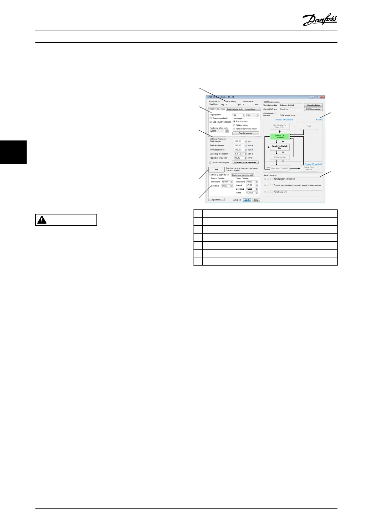
The Drive Control sub-tool elements are shown in
Illustration 5.38 and described in the following sections:
1 Actual position, velocity, and torque
2 DS402 state machine control
3 Status information area
4 Control loop parameters
5 Halt control area
6 Additional parameters area
7 Mode of operation controls
Illustration 5.38 Drive Control Sub-tool
Position, velocity, and torque actual value
The Actual position (see chapter 7.7.5 Parameter 50-03:
Position Actual Value (0x6064)), Actual velocity (see
chapter 7.11.3 Parameter 50-04: Velocity Actual Value
(0x606C)), and Actual torque value (see
chapter 7.12.5 Parameter 52-31: Torque Actual Value (0x6077))
elds are cyclically updated from the servo drive if the ISD
Toolbox is connected via cyclic communication. The elds
are read-only values. The units of the values can be set in
the Options window (see chapter 5.5.8 Options Window).
Mode of operation controls
The Modes of Operation control is a tab consisting of the
supported modes of operation. Switching to a mode of
operation is not done by only selecting its respective tab,
but by explicitly using the mode-specic control.
Mode of operation controls – Prole Position Mode tab
The Prole Position Mode control is operated by setting a
target position (set-point) and transferring it to the drive.
Set the value of the Target position eld using the numeric
up-down buttons and click on the Transfer set-point button.
The Target position value is shown in the position unit set
in the Options window (see chapter 5.5.8 Options Window).
Illustration 5.39 shows the Drive Control sub-tool with an
activated Prole Position Mode control. Prole velocity,
acceleration, and deceleration can be set using the
Operation with ISD Toolbox
VLT
®
Integrated Servo Drive ISD
®
510 System
132 Danfoss A/S © 01/2017 All rights reserved. MG36D102
55

 Loading...


