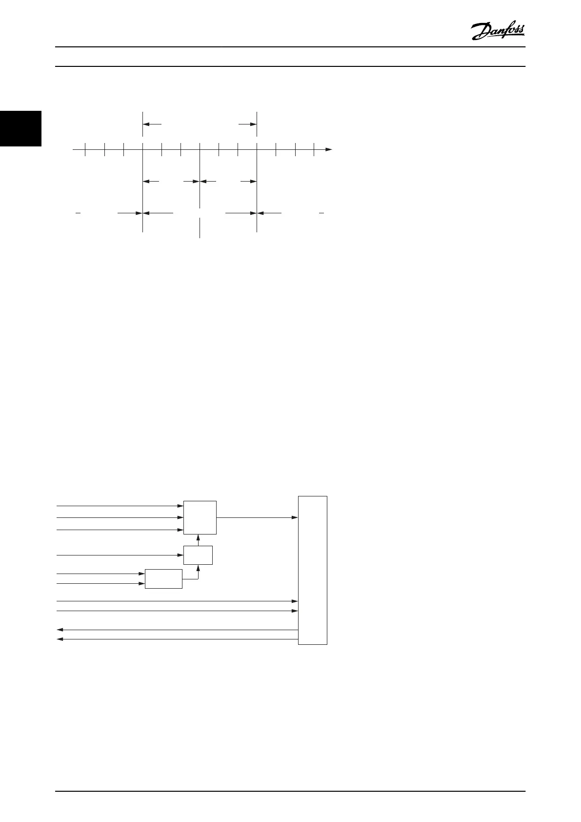
Accepted velocity range
Velocity
window
Velocity not
reached
Velocity not
reached
Velocity reached
Target
velocity
Velocity
Velocity
window
Illustration 2.22 Velocity Reached Window
2.4.3 Prole Torque Mode
In Prole torque mode, the servo drive is operated under torque control and executes a movement with constant torque.
Linear ramps are used. Additional parameters, such as the torque ramp and maximum velocity can be parameterized. This
functionality can be commanded using function block MC_TorqueControl_ISD51X (see chapter 6.5.5.8 MC_Torque-
Control_ISD51x).
The
Prole torque mode allows transmitting the target torque value (see chapter 7.12.1 Parameter 52-30: Target Torque
(0x6071)), which is processed via the trajectory generator. The torque slope (see chapter 7.12.7 Parameter 52-32: Torque Slope
(0x6087)) is required. The servo drive supports linear ramps for calculation of the trajectory generation. If the Controlword bit
8 (Halt) is switched from 0 to 1, or from 1 to 0, then the trajectory generator ramps its control eort output down to 0, or
up to the target torque. In both cases, the trajectory generator uses the torque slope for the ramp calculation.
Trajectory
generator
Limit
function
Torque
control
and
power
stage
Target torque (0x6071)
Target slope (0x6087)
Max torque (0x6072)
Prole velocity (0x6081)
Torque demand (0x6074)
Velocity limit
Minimum
comparator
Max prole velocity (0x607F)
Max motor speed (0x6080)
Motor rated torque (0x6076)
Motor rated current (0x6075)
Torque actual value (0x6077)
Current actual value (0x6078)
Illustration 2.23 Prole Torque Mode Control Function
Torque reached function
The Torque reached function oers the possibility to dene a torque range around a torque demand value to be regarded as
valid. If the torque of the servo drive is within this area (see chapter 7.12.8 Parameter: Torque Window (0x2050)) for a specied
time, the torque window time (see chapter 7.12.9 Parameter: Torque Window Time (0x2051)) and the related control bit 10
Target reached, in the Statusword is set to 1.
Servo Drive Operation
VLT
®
Integrated Servo Drive ISD
®
510 System
32 Danfoss A/S © 01/2017 All rights reserved. MG36D102
22

 Loading...


