5.7.3.10 Online and Oine Mode
Scope is available in online and oine mode.
When operating in Online mode, the full Scope
functionality is available, including conguring and
performing traces on the device. Oine mode oers the
possibility to open, view, and analyze saved traces.
When operating in Online mode, the Scope sub-tool uses
the trace signal description directly from the device; when
using Oine mode, Scope uses the local Toolbox congu-
ration instead.
When going online with the device or starting Scope for a
device that is already online, the trace signal description
and sampling rates are automatically downloaded from the
device and updated. Furthermore, the device is automat-
ically checked for available trace data.
For Oine devices, the local ISD Toolbox conguration is
used to show the sampling rates.
5.7.3.11 Reports, Document Exporting, and
Printing
For documentation and printing purposes, the Scope oers
a trace reporting functionality that generates a printable
view of the trace. It also facilitates export to a PDF or
spreadsheet le, and direct printing.
Illustration 5.35 Scope Report
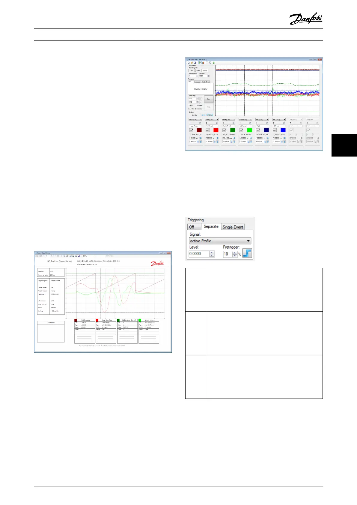
5.7.3.12 Multi-device Scope
The Multi-device scope sub-tool itself looks similar to the
single scope sub-tool, but has a list of devices inside the
tool strip. While tracing, an additional window shows the
status for all selected devices.
It is also possible to trace signals across dierent devices.
Therefore every channel has an additional drop-down box
where the device can be selected for each channel.
The result of all traces is shown in the same diagram (see
Illustration 5.36).
Illustration 5.36 Result of All Traces
It is possible to mix tracing across dierent device types,
so it is possible to trace, for example, the power of an SAB
together with the position of a servo drive.
There are dierent possibilities available for triggering (see
Illustration 5.37):
O No triggering takes place. The devices involved all do
an individual trace. They start immediately after the
Run button has been pressed. The rst sample of
device 1 is not necessarily taken at exactly the same
time as the rst sample of device 2. There is a short
delay between the devices.
Separate All devices involved trigger individually but on the
same signal. This signal must be available on all
involved devices. Therefore, the Scope reduces the
trigger signals to these signals that are available on all
devices (also across device types!) that are involved in
the tracing.
Single
event
The trigger condition on 1 single device is congured.
As soon as this event occurs, all other devices trigger
too. The devices that listen to the triggering device
take their rst sample with a short delay as the trigger
event must rst be communicated. However, their
traces are taken at exactly the same time.
Illustration 5.37 Multi-device Scope – Triggering
Operation with ISD Toolbox Programming Guide
MG36D102 Danfoss A/S © 01/2017 All rights reserved. 131
5 5

 Loading...


