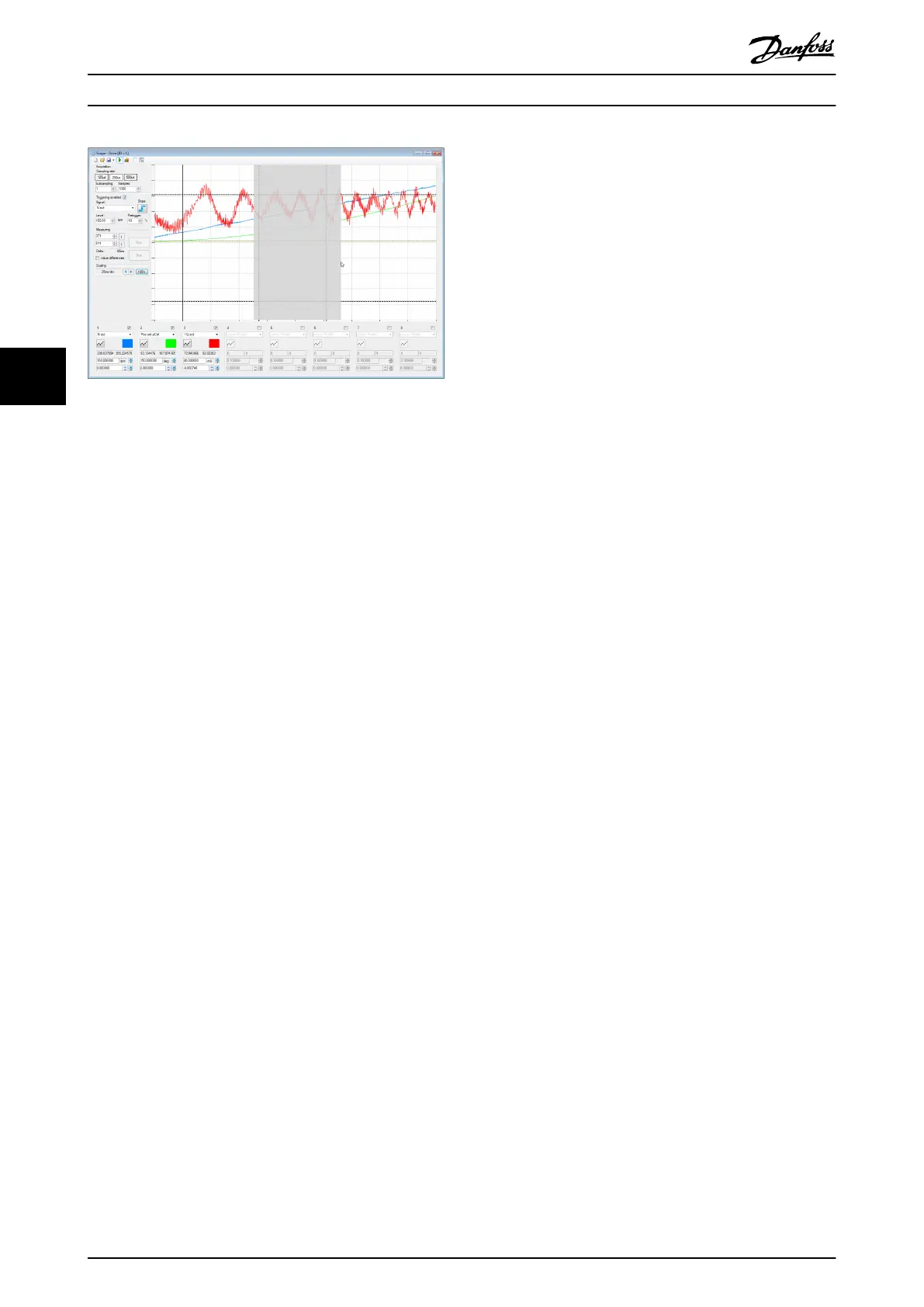
Illustration 5.34 Graphical Zoom In using the Mouse
The Scope can perform automatic scaling and oset of the
trace signals. The scaling and oset behavior depends on
the state of Scope in which the trace is shown. There are 3
dierent auto-scale modes in Scope:
•
Zero-centred (Ctrl+1)
•
Aligned and zero-centred (Ctrl+2)
•
Maximized (Ctrl+3)
The Maximized (Ctrl+3) and Zero-centred modes perform
the scaling and oset separately for each signal without
any aligning between channels. The Aligned and zero-
centred mode performs the same scale and oset on
signals with the same unit.
The Zero-centred (Ctrl+1) auto-scale mode sets the vertical
zero-point of each signal to be in the middle of the chart
area and the global maximum of the signal to be at about
10% below the top of the chart.
The Aligned and zero-centred (Ctrl+2) auto-scale mode
groups the channels by signal unit and performs the same
scaling for every channel in a group. It sets the vertical
zero-point of each signal to be in the middle of the chart
area. For each group, it sets the signal with the highest
amplitude to have a global maximum at most at about
10% below the top of the chart and a global minimum at
least at about 10% above the bottom of the chart. All
other signals in the same group are set the same scale.
The Maximized (Ctrl+3) auto-scale mode maximizes the
usage of the Scope chart area by scaling each trace signal
to have its global minimum at about 10% above the
bottom of the chart and its global maximum at about 10%
below the top of the chart. This way, each signal is
zoomed to a maximum while all trace samples are within
the visible vertical range.
Auto-scaling can be triggered by the following keyboard
shortcuts:
•
Ctrl+1 performs Zero-centred auto-scaling.
•
Ctrl+2 performs Aligned and zero-centred auto-
scaling.
•
Ctrl+3 performs Maximized auto-scaling.
5.7.3.9 Saving and Loading Data
The Scope sub-tool can save trace data and trace settings
in various ways:
•
ISD trace les (.isdtrc)
- Full measurement range
- Cursor-selected measurement range
•
Trace settings (.isdtrs)
•
Pattern le (.dat)
A trace can be opened by double-clicking on the le itself
(for example in Windows Explorer) or by selecting menu
entry [File → Open → Scope trace] and then selecting
the .isdtrc le.
ISD trace les (.isdtrc)
Scope can save and load trace data with the extension
*.isdtrc. The le contains the data of the recorded trace and
the display information (scaling factors, osets, and colors).
Measurement range (.isdtrc)
Sometimes, it is required to cut out unneeded data. In this
case, Scope can save the trace data of a given range within
the shown trace. To store only a subset of the trace, set
the vertical cursors to the start and end of the range to be
saved and then select the drop-down option Save
measurement range. The format and information that is
saved is the same as when saving the full range.
Trace settings (.isdtrs)
In order to save and restore a given trace
conguration
and visualization parameters, it is possible to save only
these settings as an ISD trace settings le. The structure of
the le is the same as the structure of the trace settings
section of the .isdtrc le format but without the data itself.
When opening an .isdtrs le with the Scope, it is automat-
ically applied.
Pattern le (.dat)
To perform a pattern search with the drive in Advanced
CAM mode (see chapter 2.4.5.5 Advanced CAM), it is
necessary to rst record a pre-dened pattern. Trace the
signals Pattern Sensor Act Even and Pattern Sensor Act Odd
and mark the pattern with the vertical cursors at the start
and the end of the pattern to be found. Then save it via
the drop-down option Save Pattern As in the drop-down
menu of the Save button.
Operation with ISD Toolbox
VLT
®
Integrated Servo Drive ISD
®
510 System
130 Danfoss A/S © 01/2017 All rights reserved. MG36D102
55

 Loading...


