button to save the le. The Save error history button is
disabled until the error history is read for the rst time.
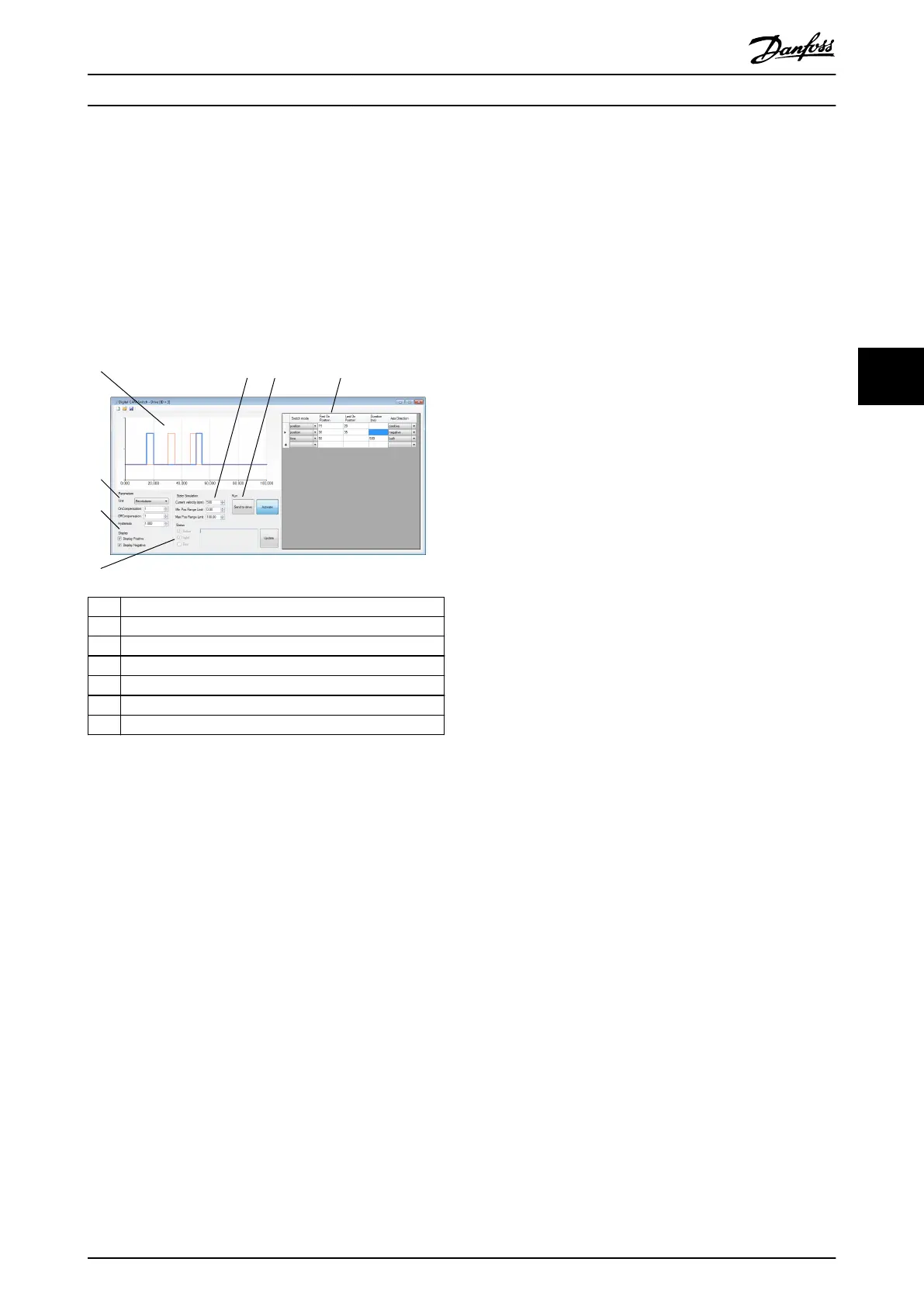
5.7.6 Digital CAM Switch (Servo Drive only)
The Digital CAM Switch sub-tool is used to create and
visualize digital CAM switch congurations, import and
export them to .dcs les, and transfer and activate them to
ISD servo drives. Illustration 5.46 gives an overview of the
Digital CAM Switch sub-tool.
1 Plot area
2 Simulation controls
3 Run controls
4 Switch denitions table
5 Status area
6 Display area
7 Parameters area
Illustration 5.46 Digital CAM Switch Sub-tool
The Parameters area contains the global switch congu-
ration. It consists of the parameters Unit (User or
Revolutions), On compensation, O compensation, and
Hysteresis. The On compensation and O compensation
values are given in milliseconds. Depending on the
selected unit, the Hysteresis value is interpreted either as
user-dened units or as revolutions. The Hysteresis eld
contains 3 decimal places that are only evaluated if the
selected unit is Revolutions. If the selected unit is User,
then only the integer part of the Hysteresis value is taken
into account.
The switch denitions table contains all switches that build
up the conguration. Every switch entry consists of the
elds Switch mode (position or time), First On Position, and
Axis Direction (positive, negative, or both).
When using switch mode position, set the Last On Position
parameter. When using the switch mode time, set the
Duration (ms) parameter. Depending on the selected unit
in the parameters area, the First On Position and Last On
Position parameters are interpreted either as user-dened
units (User) or as Revolutions.
The State Simulation and Display controls are used only for
visualization purposes and have no eect on the digital
CAM switch conguration. The horizontal plot area range is
set according to the values in the simulation elds Min Pos
Range Limit and Max Pos Range Limit. Depending on the
eld Current velocity (rpm), the length of time switches in
position units is calculated and visualized.
In the Display area, the checkboxes Display Positive and
Display Negative control if the switches in positive and
negative direction are visualized in the plot area.
The plot area graphically visualizes the digital CAM switch
denition. The horizontal plot range is dened by the
simulation parameters Min Pos Range Limit and Max Pos
Range Limit. The vertical plot axis is discrete, with values
indicating if the digital output is inactive (0) or active (1) at
any position within the plot range, given the specied
simulation velocity. Switches in positive direction are
visualized by a light blue line and switches in negative
range are visualized using a thin red line. For switches that
are dened in both directions, both a positive and a
negative visualization is made. By enabling or disabling the
visualization in positive or negative direction using the
checkboxes in the Display area, it is possible to visually
isolate and observe the resulting digital output value when
the servo drive is running in either a positive or negative
direction.
The Run controls can only be used for online servo drives.
The Send to drive button saves the digital CAM switch
conguration to a temporary le and then transmits it to
the servo drive using the le transfer protocol that is
available on the current eldbus. The Activate button sends
an activation command to the servo drive.
The Status area can only be used for online servo drives. It
shows the actual status of the digital CAM switch
functionality on the servo drive. It contains the read-only
checkboxes Active, Valid, and Error, corresponding to the
active, valid, and error bits in the digital CAM switch
parsing state object. If an error occurs, the corresponding
error text is shown in the read-only text eld in the Status
area. The status can only be manually updated using an
SDO transfer, which can be triggered by using the Update
button.
The Digital CAM Switch sub-tool can save and load digital
CAM switch congurations using the save and load
buttons in the toolbar.
Operation with ISD Toolbox Programming Guide
MG36D102 Danfoss A/S © 01/2017 All rights reserved. 137
5 5

 Loading...


