between the beginning of the event segment
container and the selected predecessor node. This
is necessary because event nodes do not have x-
coordinates and therefore, the starting point of
an event segment is calculated from its
predecessors, which leads back to the beginning
of the event segment container.
•
When creating a Time poly, its duration parameter
is set according to the end position selected and
a succeeding event node is always created for the
Time poly.
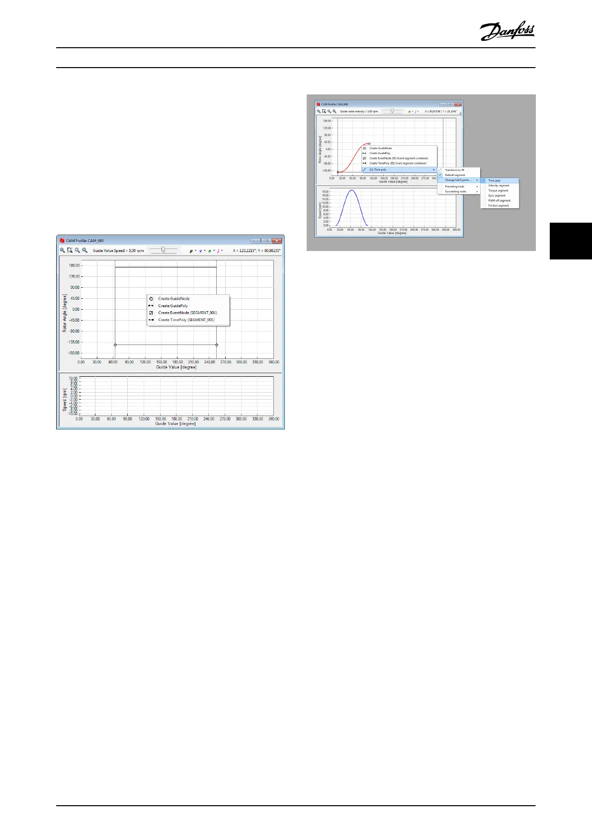
Illustration 5.71 Advanced CAM Editing: Event-Based Context
Menu
For event segments, the Change SubType to . . . entry allows
switching a segment between the following types:
•
Time poly
•
Velocity segment
•
Torque segment
•
Sync segment
•
PWM o segment
•
Friction segment
Illustration 5.72 presents the event segment context menu
with its transformation options.
Illustration 5.72 Event Segment Context Menu
Common segment properties
This section lists the common properties of all guide
segments and event segments. The properties are
organized in the following property groups:
•
Parameters
- ID: Unique segment ID within the CAM
prole.
- Segment type: Read-only property for
helping the user verify the segment
type. The value is Guide segment or
Event segment.
- Sub-type: The sub-type of the segment
(for example, Guide poly or Move
distance segment for guide segments,
and Time poly or Velocity segment for
event segments).
- Default: Species if the segment is the
default segment for its preceding node.
•
Relations
- Preceding node: Contains the preceding
node of the segment.
- Succeeding node: Contains the
succeeding node of the segment.
•
Start
- Start actions: Contains the list of actions
that are performed at the beginning of
the segment.
•
End
- End actions: Contains the list of actions
that are performed at the end of the
segment.
•
Appearance
- Visible: Indicates if the segment is
shown inside the CAM Prole window.
•
Information (all read-only)
Operation with ISD Toolbox Programming Guide
MG36D102 Danfoss A/S © 01/2017 All rights reserved. 149
5 5

 Loading...


