Variable
name
Data
type
Defau
lt
value
Description
VAR_IN_OUT
Axis Chapter 6.5.4.1
AXIS_REF_ISD
51x
Reference to the axis.
See chapter 6.5.4.1 AXIS_REF_ISD51x.
VAR_INPUT
Enable BOOL FALSE If this input is TRUE, power is being
enabled.
TimeLimit TIME t#0ms Time after which an error is
signaled, if Status has not changed
to TRUE while Enable is TRUE. Set
the value to 0 to disable the time
limit.
VAR_OUTPUT
Status BOOL Eective state of the power stage.
Valid BOOL If TRUE, the function block has a
valid set of outputs.
Error BOOL An error has occurred within the
function block.
ErrorInfo DD_ERROR_IS
D51x
Error identication and instance
identier.
See chapter 6.5.2.3 Error Indication.
Table 6.3 MC_Power_ISD51x
If the MC_Power_ISD51x function block is called up and the
variable Enable is TRUE while in PLCopen state Disabled,
the axis state changes to Standstill.
Error is set to TRUE if the Enable input is TRUE for the time
specied in the input TimeLimit, while the Status remains
FALSE. It indicates a hardware problem with the power
stage. If power fails (also during operation), it generates a
transition to the ErrorStop state.
Only 1 MC_Power_ISD51x function block can be issued per
axis.
The Enable input in this function block is not an Enable
input as described in chapter 6.5.2.2 Function Blocks with
Enable Input. Therefore, the general rules for the Enable
input do not apply here. This function block is implicitly
enabled. The Enable input of this function block controls
the power stage of the servo drive. All outputs are always
updated (so Valid can be TRUE, even if Enable is FALSE).
The input TimeLimit represents the maximal duration of
functionality. If the TimeLimit is exceeded during switching
on the servo drive, an Error is signaled on the outputs.
However, the functionality according to the Enable input is
continued. This means that the function block still tries to
enable the servo drive, if Enable is set to TRUE, and/or to
disable the servo drive if Enable is set to FALSE. If the servo
drive starts reacting again, the Error output can change to
FALSE again without a new rising edge of Enable. Set the
value to 0 to disable the limiting functionality.
The command is transferred immediately, but it can take
some time until the axis is powered up and the output
Status becomes TRUE.
6.5.4.3 MC_Reset_ISD51x
This function block commands the transition from the state
ErrorStop to Disabled by resetting all internal axis-related
errors. It does not aect the output of the function block
instances.
The command is transferred and executed immediately.
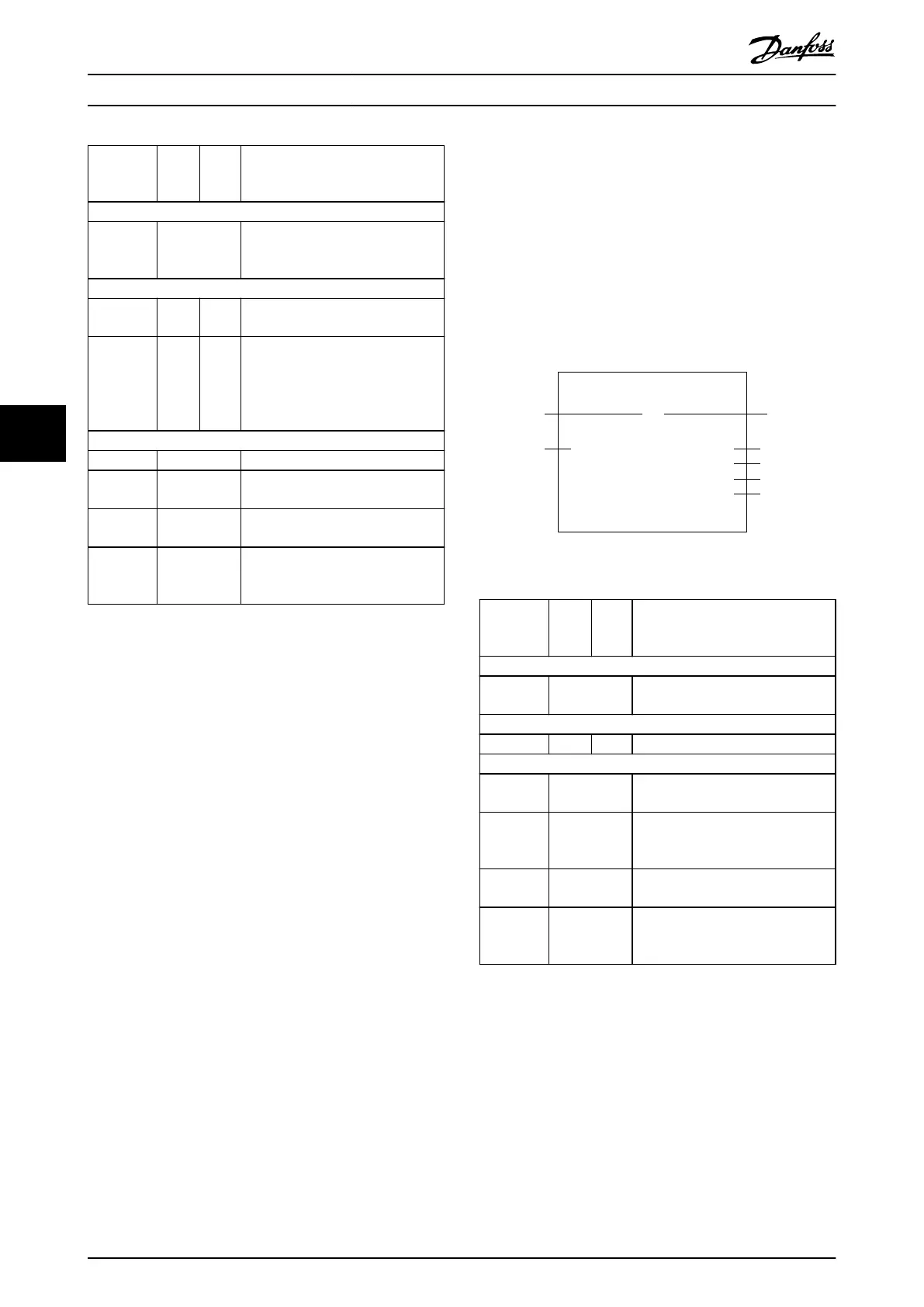
MC_Reset_ISD51x
Axis
ExecuteBOOL
AXIS_REF_-
ISD51x
BOOLDone
BOOLBusy
BOOL
DD_ERROR_-
ISD51x
ErrorInfo
Error
Illustration 6.26 MC_Reset_ISD51x
Variable
name
Data
type
Defau
lt
value
Description
VAR_IN_OUT
Axis AXIS_REF_ISD
51x
Reference to the axis.
See chapter 6.5.4.1 AXIS_REF_ISD51x.
VAR_INPUT
Execute BOOL FALSE Resets all internal axis-related errors.
VAR_OUTPUT
Done BOOL Error was reset and state Disabled
reached.
Busy BOOL The function block is not nished
and new output values are to be
expected.
Error BOOL An error has occurred within the
function block.
ErrorInfo DD_ERROR_IS
D51x
Error identication and instance
identier.
See chapter 6.5.2.3 Error Indication.
Table 6.4 MC_Reset_ISD51x
Programming
VLT
®
Integrated Servo Drive ISD
®
510 System
178 Danfoss A/S © 01/2017 All rights reserved. MG36D102
6
6

 Loading...


