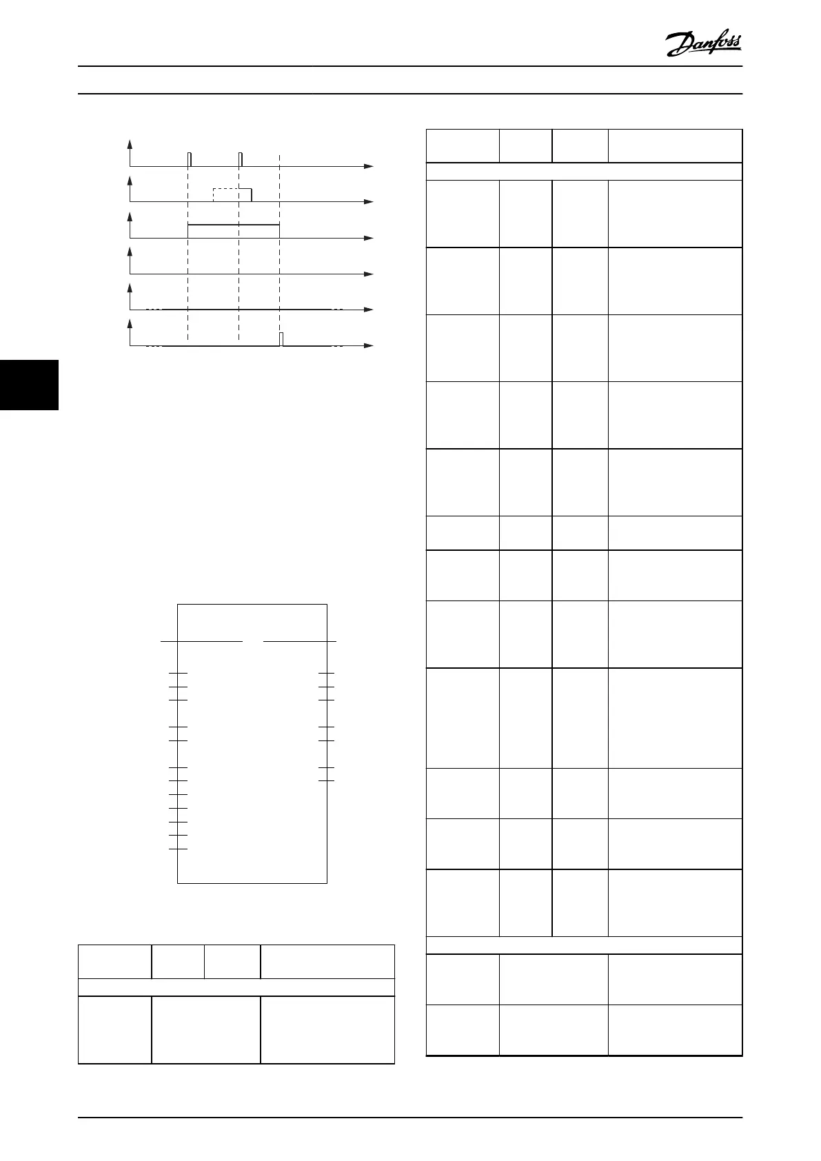
Execute
Abort
Busy
Done
Command
Aborted
Start
functionality
Abort
functionality
Error
130BE949.10
Illustration 6.49 Behavior When an Error Occurs During Abort
of Functionality
A value of 0 is not allowed for the inputs pTraceBuer,
TraceBuerSize, SampleCount, and SubSampling. For the
input SignalIDs, at least the 1
st
element of the array must
be >0, otherwise the function block signals an error.
For the input SampleCount, the value, multiplied by the
number of valid SignalIDs, must not exceed the TraceBuf-
ferSize and must not exceed the maximum available trace
buer size of the servo drive (see chapter 2.7.2 Trace).
DD_Trace_ISD51x
Axis
ExecuteBOOL
AXIS_REF_ISD51x
BOOLDone
BOOLBusy
BOOLError
BOOL
DD_ERROR_-
ISD51x
ErrorInfo
USINTStatus
UDINTTraceLength
Command
Aborted
AbortBOOL
TraceBuerSizeUDINT
SamplingRateDD_SAMPLING_-
RATE_ISD51x
SampleCountUINT
SubSamplingUINT
SignalIDsARRAY[0..7] OF UDINT
TriggerIDUDINT
TriggerPointUSINT
TriggerLevelREAL
TriggerSlopeBOOL
pTraceBuerUDINT
Illustration 6.50 DD_Trace_ISD51x
Variable
name
Data
type
Default
value
Description
VAR_IN_OUT
Axis AXIS_REF_ISD51x Reference to the axis.
See
chapter 6.5.4.1 AXIS_REF_IS
D51x.
Variable
name
Data
type
Default
value
Description
VAR_INPUT
Execute BOOL FALSE Starts the trace
functionality at rising edge
and keeps on polling until
the data is available.
Abort BOOL FALSE Abort the ongoing trace.
New values are only
evaluated on a rising edge
of Execute.
pTraceBuer UDINT 0 Reference to a buer
where the read trace data
will be placed; Use ADR()
function
TraceBuf-
ferSize
UDINT 0 Size of the trace buer;
use SIZEOF() function.
Size of the provided buer
given in Byte.
SamplingRate DD_SAM
PLING_RA
TE_ISD51
x
ddFastTas
k_ISD51x
Sampling rate of the trace.
SampleCount UINT 4000 Number of samples to be
traced per channel.
SubSampling UINT 1 Multiplier to adjust time
dierence between trace
samples.
SignalIDs ARRAY[0..
7] of
UDINT
[0, 0, 0, 0,
0, 0, 0, 0]
IDs of the signals to be
traced. Available in the list
of constants: AxisTrace-
Signals.
TriggerID UDINT 0 ID of the signal used for
triggering. Available in the
list of constants: AxisTrace-
Signals.
Set the value to 0 for
instant tracing.
TriggerPoint USINT 10 Amount of pre-trigger
history [in percentage].
Value range: 0–100
TriggerLevel REAL 0.0 Level at which the device
triggers (in trigger signal
units).
TriggerSlope BOOL TRUE TRUE: Triggers on rising
slope.
FALSE: Triggers on falling
slope.
VAR_OUTPUT
Done BOOL The trace has successfully
been recorded and read
from the device.
Busy BOOL The function block is not
nished and new output
values are to be expected.
Programming
VLT
®
Integrated Servo Drive ISD
®
510 System
192 Danfoss A/S © 01/2017 All rights reserved. MG36D102
6
6

 Loading...


