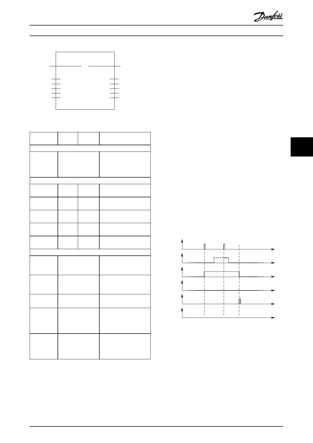
DD_WriteParameter4_ISD51x
Axis
ExecuteBOOL
AXIS_REF_-
ISD51x
BOOLDone
BOOLBusy
DD_ERROR_ISD51xErrorInfo
BOOL
DWORDAbortCode
Error
IndexUINT
LengthUSINT
Subindex
ValueDWORD
USINT
130BE277.10
Illustration 6.47 DD_WriteParameter4_ISD51x
Variable
name
Data
type
Default
value
Description
VAR_IN_OUT
Axis AXIS_REF_ISD51x Reference to the axis.
See
chapter 6.5.4.1 AXIS_REF_IS
D51x.
VAR_INPUT
Execute BOOL FALSE Write the value of the
parameter at rising edge.
Index UINT 0 Index of the object to be
written.
Subindex USINT 0 Sub-index of the object to
be written.
Length USINT 0 Length of the data to be
written [Byte].
Value DWORD 0 New value of the specied
parameter.
VAR_OUTPUT
Done BOOL The value has successfully
been written to the
device.
Busy BOOL The function block is not
nished and new output
values are to be expected.
Error BOOL An error has occurred
within the function block.
ErrorInfo DD_ERROR_ISD51x Error identication and
instance identier.
See chapter 6.5.2.3 Error
Indication.
AbortCode DWORD SDO abort code if there is
an error. Available in the
list of constants:
SdoAbortCodes.
Table 6.25 DD_WriteParameter4_ISD51x
6.5.4.24 DD_Trace_ISD51x
This function block is used to carry out a real-time trace
within the axis using the settings given in the input
variables. When the settings are sent and the trace started,
the function block automatically polls the axis until the
data has been recorded and then uploads the data
automatically. Information about the status of the tracing
can be monitored using the Status output (while Busy is
TRUE).
Inside the axis, the data is sampled over time, meaning
that there is an adjustable time dierence between the
samples (use inputs SamplingRate and SubSampling). For
general tracing capabilities, refer to chapter 2.7.2 Trace.
The Abort input is used to abort the current functionality.
The output CommandAborted is used to signal a successful
aborting procedure (see Illustration 6.48). The abort of the
functionality can take some time.
The behavior of output CommandAborted is similar to the
Done output, only for a successful aborting procedure.
If there is an error during aborting, the Error output is set
to TRUE and the error reason is indicated at output
ErrorInfo. The output CommandAborted stays as FALSE in
this case (see Illustration 6.49).
For function blocks with Execute as Abort input, the Abort
input (and any other inputs of the function block) is only
evaluated at a rising edge of Execute.
Execute
Abort
Busy
Done
Command
Aborted
Start
functionality
Abort
functionality
Error
130BE948.10
Illustration 6.48 Behavior of Successful Abort of Functionality
Programming Programming Guide
MG36D102 Danfoss A/S © 01/2017 All rights reserved. 191
6
6

 Loading...


