Physical (Absolut) Position
Position Actual Internal
Value
(0x6063)
[increments]
(-)
TRC_ROTOR_POS
[increments]
Position oset =
permanent position oset + temporary position oset
(temporary position oset is set during homing)
130BF570.10
Illustration 2.27 Position Oset Denition
=>420°–360°=60°
Range limit: 0–360°
Home oset 420°
Home oset 180°
Current position
=home position (method 37)
60°
180°
360° 720°
720°360°
40°
360°0° 720°
0°
130BF178.10
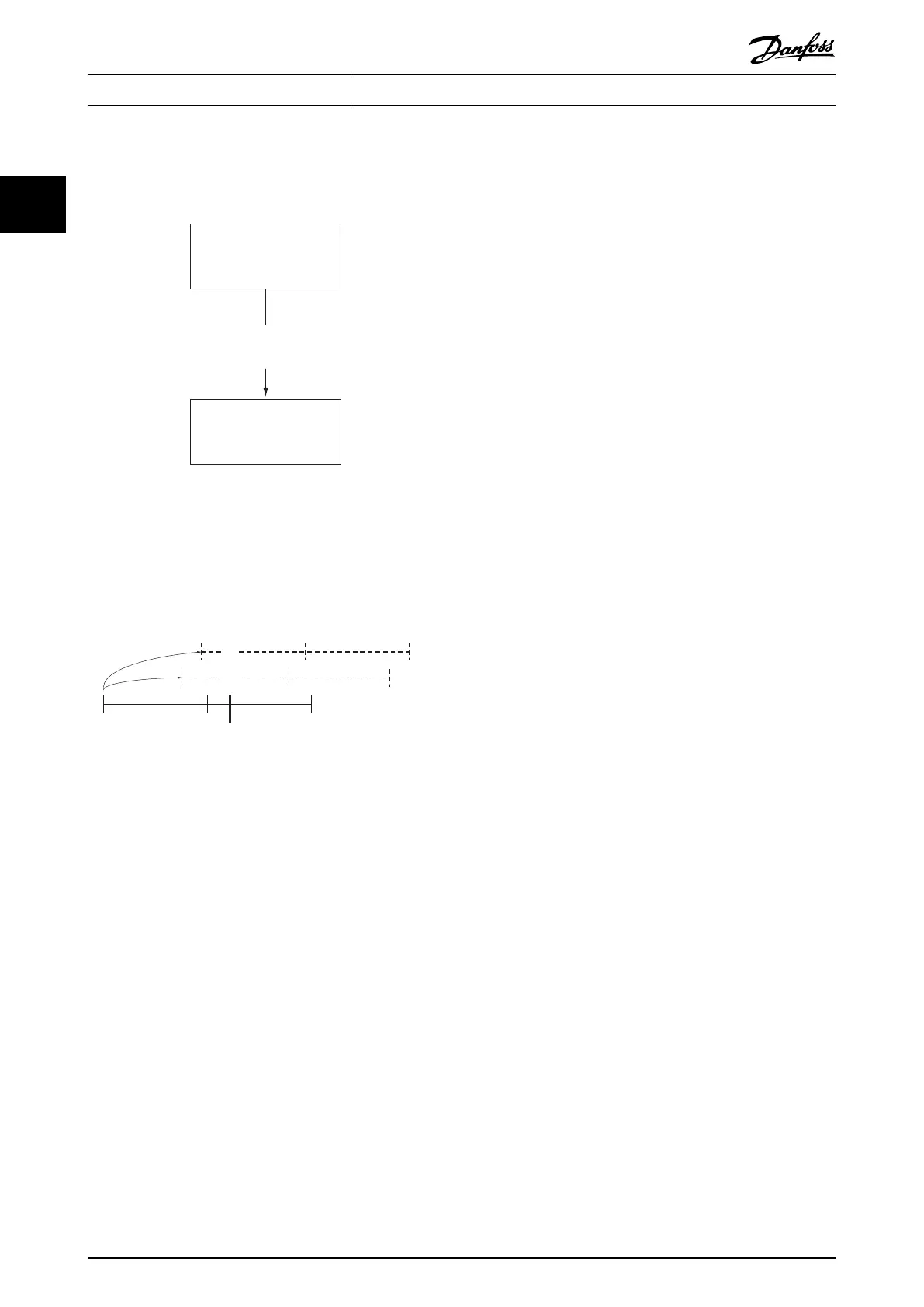
Illustration 2.28 Behavior of Homing with Software Range
Limit Applied
In Illustration 2.28, the lowermost solid line shows the current physical position of the servo drive. The software range limit is
applied so that the servo drive shows position actual values between 0° and 360°. The bold vertical line shows the current/
reference position, where the servo drive shows 40°. The ne dashed line in the middle shows the situation when activating
homing method 37 (Homing on current position) with a value for the home oset (0x607C) of 180°. The position actual value
(0x6064) shows 180°. The multi-turn revolutions are discarded. The bold dashed line at the top shows the situation when
activating homing method 37 (Homing on current position) with a value for the home oset (0x607C) of 420°. The position
actual value (0x6064) shows 60°. The multiples of the software range limit from the home oset are discarded.
The reference position found during homing is lost after a reset. However, it is possible to save this reference position
permanently (see sub-index 3 in chapter 7.7.8 Parameters 51-02, 52-04, and 52-49: Application Settings (0x2016) for details). The
homing bit is not set after a power-cycle, however the position is preserved.
Servo Drive Operation
VLT
®
Integrated Servo Drive ISD
®
510 System
34 Danfoss A/S © 01/2017 All rights reserved. MG36D102
22

 Loading...


