chapter 7.13.3 Parameters 52-42 and 52-43: Homing Speeds (0x6099)) until the switch is no longer active (falling edge). The
home position of the servo drive is at this edge. The motor ramps down to 0 velocity and the successful homing procedure
is reported. If the homing procedure is started and the limit switch is already set, the servo drive immediately signals a
homing error.
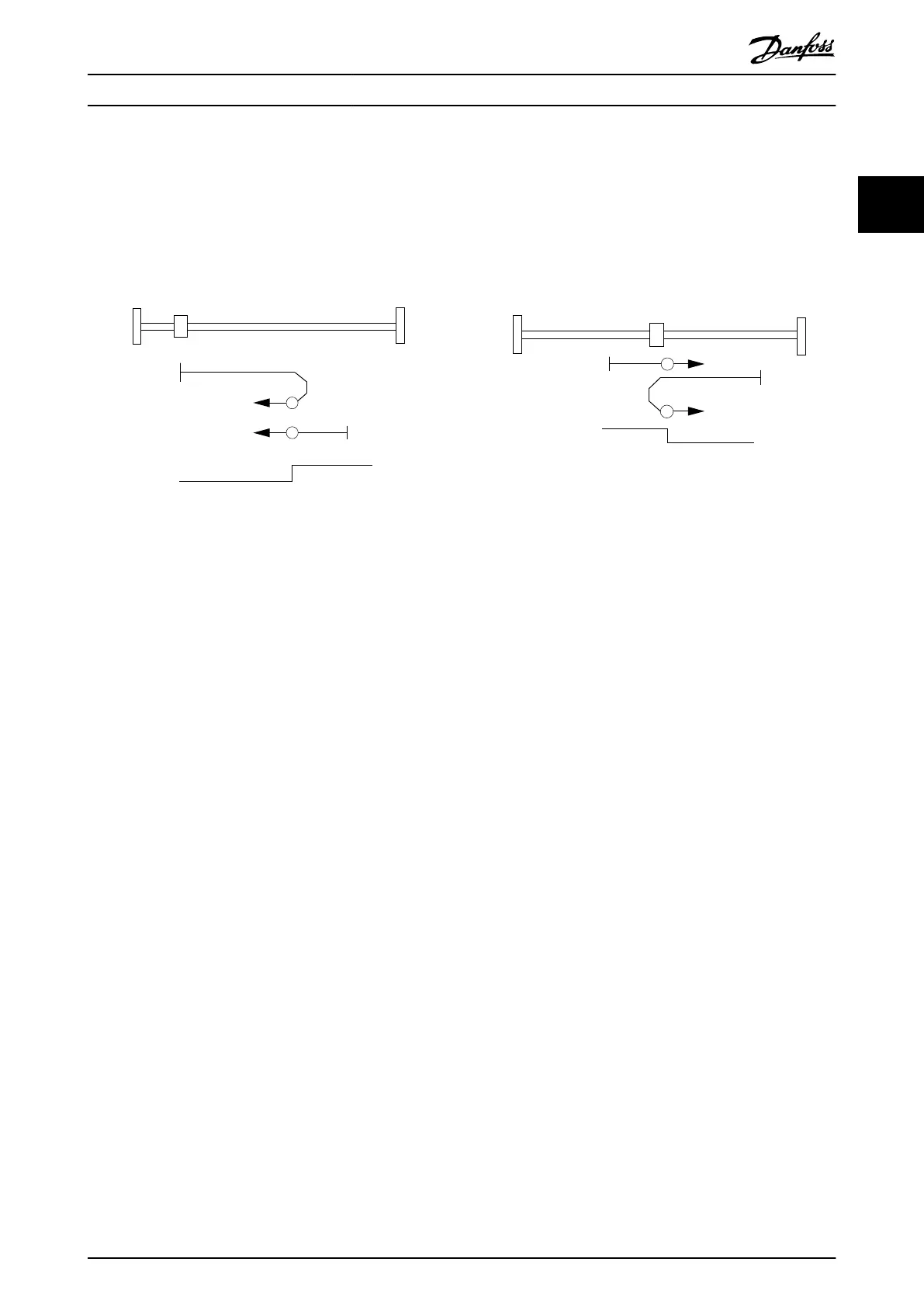
2.4.4.4 Homing on Positive/Negative Home Switch
19
19
Home Switch
130BF181.10
Illustration 2.33 Homing Method 19: Homing on Positive
Home Switch
Home Switch
21
21
130BF182.10
Illustration 2.34 Homing Method 21: Homing on Negative
Home Switch
Homing method 19 (positive) or 21 (negative) can be used if a home switch is available and can be congured using object
0x200F (see chapter 7.21.3 Parameter: Dual Analog User Inputs Conguration (0x200F)) so that the home switch signals the
home reference point.
The initial movement depends on the logical state of the home switch at activation. In all cases, the servo drive turns with
the velocity set in object 0x6099, sub-index 01: Speed during search for switch (see chapter 7.13.3 Parameters 52-42 and
52-43: Homing Speeds (0x6099)) until it encounters a signal change of the home switch. The servo drive reverses direction
and ramps to the velocity set in object 0x6099, sub-index 02: Speed during search for zero until the home switch changes
states again. The home position of the servo drive is at this edge. The motor ramps down to 0 velocity and the successful
homing procedure is reported.
The dierences between the 2 methods are:
•
Positive home switch (19): During activation of the homing procedure, a low state of the home switch leads to the
servo drive moving in a positive direction. A high state of the home switch leads to the servo drive moving in a
negative direction.
•
Negative home switch (21): During activation of the homing procedure, a low state of the home switch leads to
the servo drive moving in a negative direction. A high state of the home switch leads to the servo drive moving in
a positive direction.
2.4.4.5 Homing on Current Position
In this method (37), the current position of the servo drive is used as the home position. This method does not require the
servo drive to be in state Operation enabled because no movement occurs. If the servo drive is in state Operation enabled
during activation, it must be in standstill.
At the home position, the Position oset is calculated so that the value of the Position actual value (see
chapter 7.7.5 Parameter 50-03: Position Actual Value (0x6064)) equals the Home oset (see chapter 7.13.1 Parameter 52-40: Home
Oset (0x607C)):
Position actual value (0x6064) = Home oset (0x607C)
If the value of the Home oset is higher than the Position range limit, only the modulo part is used.
Servo Drive Operation Programming Guide
MG36D102 Danfoss A/S © 01/2017 All rights reserved. 37
2 2

 Loading...


