2.4.4.6 Error Behavior in Homing Mode
For the methods where Homing limit distance (see sub-index 03: in chapter 7.13.6 Parameter 52-45 to 52-48: Additional
Homing objects (0x2040)) is used for supervising, the following error behavior applies:
If the limit is exceeded, the homing procedure is aborted. The servo drive signals a Homing error. If the servo drive is in
motion at this point of time, it ramps down with the quick stop deceleration (see chapter 7.5.9 Parameter 50-13: Quick Stop
Deceleration (0x6085)) to standstill but stays in state Operation enabled. Additionally, a warning is issued (Warning bit in
Statusword and setting of warning code).
The following situations can also lead to a warning:
•
Entering Homing mode when not in standstill.
•
Starting a homing procedure while not in standstill. A warning and a homing error are reported. If the axis reaches
standstill, the homing method is started.
•
If the homing procedure reaches the homing distance, the homing is aborted and a warning is reported.
2.4.5 CAM Mode
In CAM mode, the servo drive executes a synchronized movement based on a master axis (guide value). The synchronization
takes place by means of a CAM prole that contains slave positions corresponding to master positions. CAMs are designed
with either the CAM Editor of the ISD Toolbox chapter 5.7.7 CAM Editor (Servo Drive only) or by using special structures in the
PLC library chapter 6.5.7 Drive – CAM Creation. The guide value can be provided by an external encoder, virtual axis, or the
position of another axis.
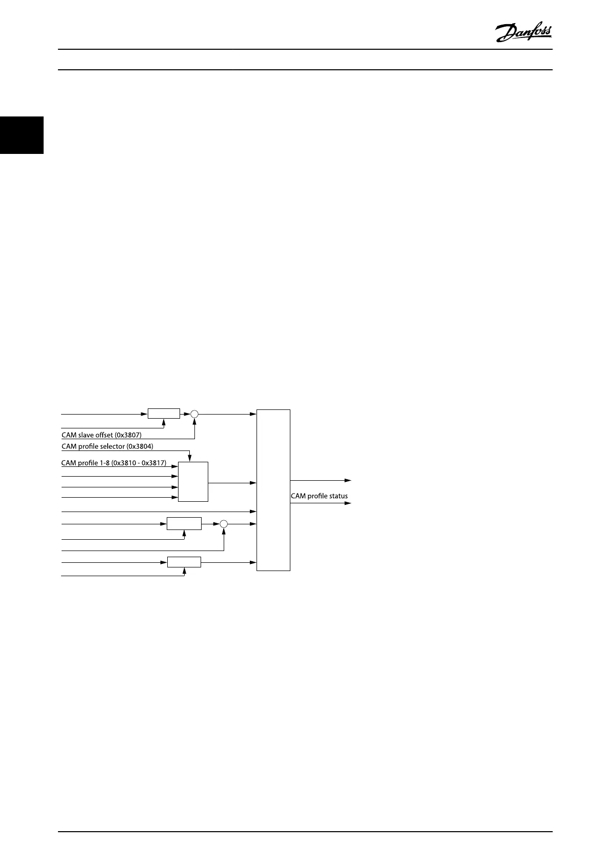
Multiplier
Logical CAM
Position (0x2020)
Selector
Multiplier
Multiplier
Trajectory
generator
Drive Position (0x2022)
CAM slave scaling (0x3809)
CAM data 1-8 (0x3820 - 0x3827)
Minimum blending distance (0x380A)
Position guide value (0x2060)
Guide value scaling factor (0x3808)
Guide value oset (0x3806)
Velocity guide value (0x2064)
Guide value scaling factor (0x3808)
+
+
Position demand
internal value
(0x60FC)
(0x3805)
130BF183.10
Illustration 2.35 Inputs for CAM Mode
When switching to CAM mode when the servo drive is not in standstill, it continues rotating with its current velocity. As
soon as a new CAM prole is activated, the new CAM prole is processed with the corresponding behavior. The servo drive
can hold a maximum of 8 CAM proles (see chapter 7.14.4 Parameters: CAM Prole 1–8 (0x3810–0x3817)). A CAM prole
consists of the CAM itself and its CAM conguration. CAM proles are automatically stored inside the servo drive.
There are 2 types of CAMs:
•
Basic CAM
A basic CAM is a list of data points that describe
the relationship between the slave position and
the master position. Each data point consists of:
- Master position
- Slave position
- Slave velocity
- Slave acceleration
•
Advanced CAM
An advanced CAM is represented by nodes,
segments, actions, and exit conditions. There are
dierent segment types that each have a special
functionality to provide intelligent application
functionality within the servo drive.
Servo Drive Operation
VLT
®
Integrated Servo Drive ISD
®
510 System
38 Danfoss A/S © 01/2017 All rights reserved. MG36D102
22

 Loading...


