MoveDistanceSegment:
MoveDistanceSegments are used for movements with no
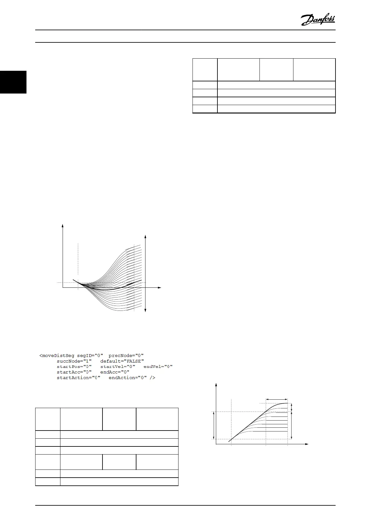
predened rotation angle. The desired rotor angle is given
to the axis during run-time. It must be given before the
beginning of the segment. It must be given in every
machine cycle (see Table 2.53 in chapter 2.4.5.6 Commands
During Operation).
This segment is mostly used together with an external
camera for object alignment. The start and end velocity,
and the start and end acceleration can be parameterized.
The parameter that is sent during run-time must be given
in revolutions of rotor angle. The rotor angle must be sent
at least 5 ms before the segment begins.
If no parameter is sent for this segment, the axis reports an
error (see chapter 2.4.5.7 Notications from the Servo Drive)
and assumes a distance of 0. An error message is sent
when passing the precNode of this segment. A new
parameter message, meant for the next cycle, can be sent
to the servo drive when the succNode of this segment has
been passed.
130BF293.10
Guide
value
Rotor angle
of axis
startPos
endVel
startVel
succNode
precNode
Distance is variable;
needs to be sent at
run-time in every
machine cycle
Illustration 2.86 MoveDistanceSegment
Illustration 2.87 Start/Endpoint Representation
Attribute
Mandatory/
optional
(+default value)
Value range/
allowed
values
Description
segID Same as in Table 2.17.
precNode Same as in Table 2.17.
succNode Same as in Table 2.17.
startPos O Float See Table 2.18 for
type= relative.
startVel Same as in Table 2.18.
endVel Same as in Table 2.18.
Attribute
Mandatory/
optional
(+default value)
Value range/
allowed
values
Description
startAcc Same as in Table 2.18.
endAcc Same as in Table 2.18.
startAction Same as in Table 2.17.
endAction Same as in Table 2.17.
Table 2.20 Attributes for MoveDistanceSegment in
Start/Endpoint Representation
Coecient representation: This representation is not
available.
FlyingStopSegment:
The FlyingStopSegment is used to stop the servo drive out
of a synchronous movement at a position, which can be
determined at run-time. This angle is usually determined
by a camera system. The motion consists of 2 parts, a
constant rotation, which length is dened by the sent
parameter, and a deceleration polynomial for stopping the
servo drive (a polynomial of 3
rd
degree is used). The angle
must be passed before the segment has started. The
parameter can be in a range from 0° to maxConstantDist.
The value is given as an absolute value. The direction is
determined by the direction of the velocity.
The rotor angle must be sent during run-time but before
the beginning of this segment. When the constant part has
been processed for the parameter, which was given, the
stopping part of the segment starts. This braking
polynomial is always the same, independent of the
remaining distance to the end of the segment.
The parameter that is sent during run-time must be given
in revolutions of rotor angle. The rotor angle must be sent
at least 5 ms before the segment begins. If no parameter is
sent for this segment, the axis reports an error (see section
Notications from the servo drive in this sub-chapter) and
assumes a distance of maxConstDist. The error message is
sent when passing the precNode of this segment. A new
parameter message, meant for the next cycle can be sent
to the servo drive when the succNode of this segment was
passed.
Guide
value
Rotor angle
of axis
startPos
succNodeprecNode
maxConstDist
startVel
brakeLength
brakeDist
Distance is variable;
needs to be sent at
run-time in every
machine cycle
130BF294.10
Illustration 2.88 FlyingStopSegment
Servo Drive Operation
VLT
®
Integrated Servo Drive ISD
®
510 System
58 Danfoss A/S © 01/2017 All rights reserved. MG36D102
22

 Loading...


