The functionalities of the SAB include:
•
Distributes and switches the U
AUX
voltage (24–48 V) that powers the control logic of the servo drives.
•
Recties the 400 V AC 3-phase mains input and switches the resulting DC bus voltage.
•
Distributes the eldbus to the hybrid cable outputs and routes it to a 2
nd
RJ45-connector for simple cabinet
cabling.
•
Connects the STO (Safe Torque O) voltages to the hybrid cables.
•
Provides a master guide value for the whole system.
•
When required, assigns the Ethernet POWERLINK
®
IDs to the connected servo drives.
•
Controls the 2 relays.
•
Dissipates the recuperation energy using an external brake resistor.
3.2 Control
To change the state of the SAB, write to the Controlword
(see chapter 8.1 Object 0x4040: Controlword). This can be
done in 2 ways:
•
Using the PLC via the eldbus.
•
Via a connected LCP in local control mode.
The actual state can be read back from the Statusword (see
chapter 8.2 Object 0x4041: Statusword). After power-up, the
U
AUX
output is activated by default and communication
with the connected servo drives is possible.
UDC cannot be activated unless U
AUX
is enabled. Deacti-
vating U
AUX
always also deactivates UDC.
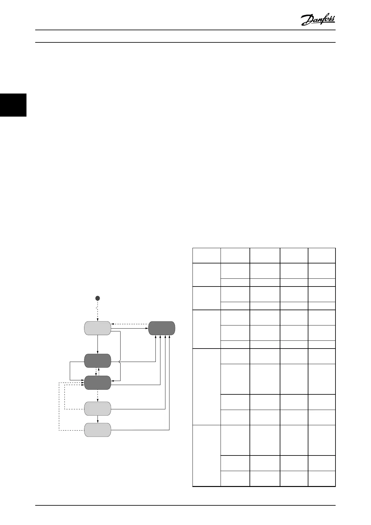
Illustration 3.2 shows the possible transitions.
Initial
Init without U
Enable U
Switch On
Error
Error
Error
Reset (Clear Errors )
Error
Error
Disable UDC
Disable UDC
Inrush SAB card nished
U is applied AND
Disable U
Init with U
Init Fault
U Disabled
Standby
Power up
Operation
Enabled
130BF037.10
AUX
AUX
AUX
AUX
AUX
AUX
AUX
Init Without U
Illustration 3.2 State Diagram with Possible Transitions
Legend:
Transitions with dashed lines: Commands (Reset, Errors,
U
AUX
control, UDC control).
Transitions with solid lines: Automatic transitions with
specied conditions.
States shaded dark gray: The control can be changed
between remote and local via the LCP.
The dened states and the possible transitions, along with
the executed actions, are dened in Table 3.1. The actual
encoding is shown in chapter 8.2 Object 0x4041: Statusword.
Current
state
Transition
command
Required
condition
Executed
action
Following
state
Init (Auto) Initialization
nished
– Standby
Error – – Fault
U
AUX
disabled
U
AUX
enable U
AUX
applied Enable
U
AUX
Standby
Error – – Fault
Standby U
AUX
disable – Disable
U
AUX
Standby
UDC enable U
AUX
1 & 2
ready
– Power-up
Error – – Fault
Power-up (Auto) Inrush
nished
– Operation
enabled
U
AUX
disable – Disable
U
AUX
Disable
UDC
U
AUX
disabled
UDC disable – Disable
UDC
Standby
Error – Disable
UDC
Fault
Operation
enabled
U
AUX
disable – Disable
U
AUX
Disable
UDC
U
AUX
disabled
UDC disable – Disable
UDC
Standby
Error – Disable
UDC
Fault
Servo Access Box (SAB) Oper...
VLT
®
Integrated Servo Drive ISD
®
510 System
90 Danfoss A/S © 01/2017 All rights reserved. MG36D102
33

 Loading...


