4 Local Control Panel (LCP) Operation
4.1 Overview
The LCP is the graphical user interface on the SAB for
diagnostic and operating purposes. It is included as
standard with the SAB but can also be connected to the
advanced servo drives using an optional cable
(M8 to LCP D-SUB extension cable).
The LCP display provides the operator with a quick view of
the state of the servo drive or SAB, depending on which
device it is connected to. The display shows parameters
and alarms/errors and can be used for commissioning and
troubleshooting. It can also be used to perform simple
functions, for example activating and deactivating the
output lines on the SAB.
The LCP can be mounted on the front of the control
cabinet and then connected to the SAB via a SUB-D cable
(available as an accessory).
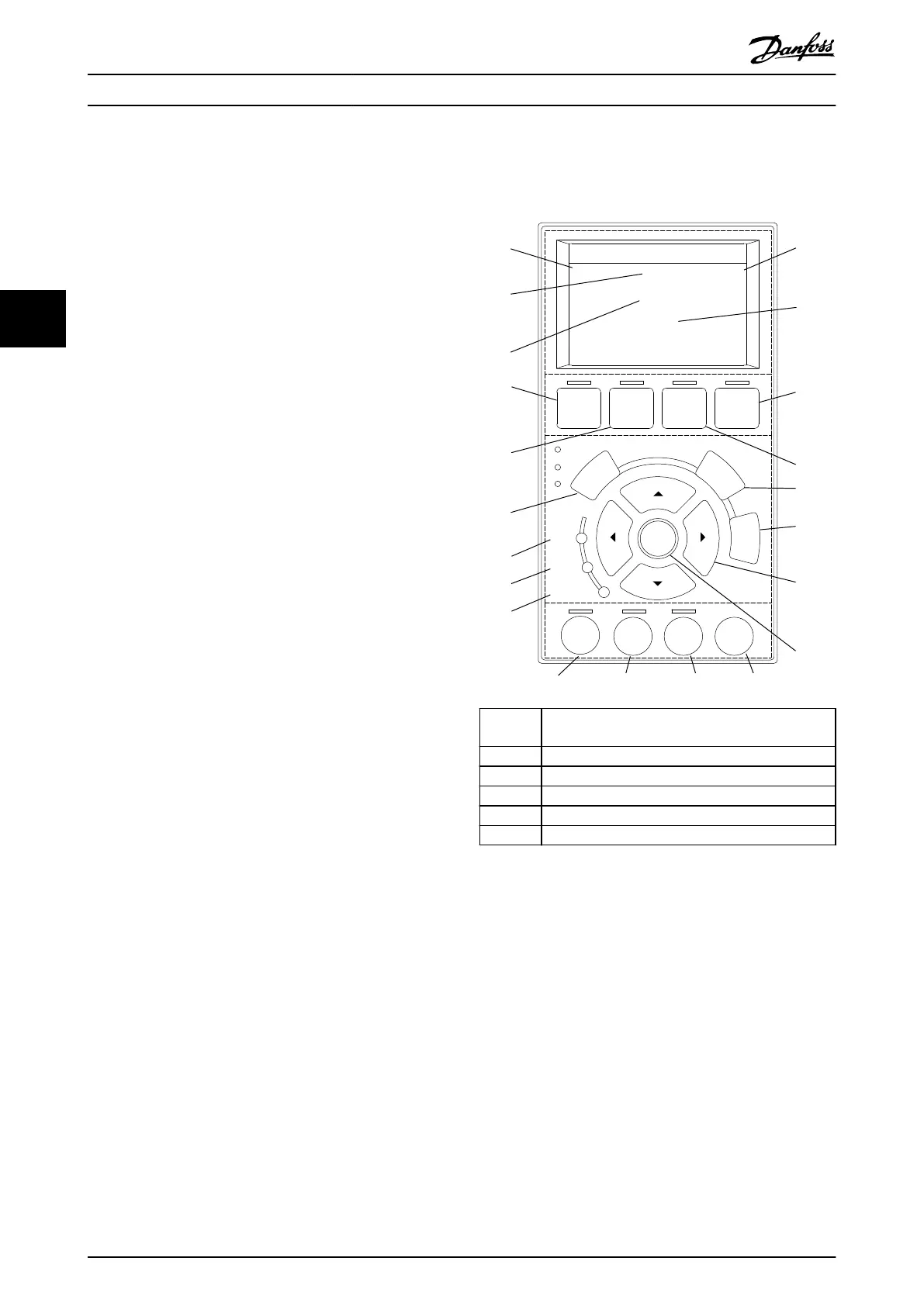
4.2 Local Control Panel (LCP) Layout
The local control panel is divided into 4 functional groups
(see Illustration 4.1).
A. Display area.
B. Display menu keys.
C. Navigation keys and indicator lights (LEDs).
D. Operation keys and reset.
A. Display area
The values in the display area dier depending on whether
the LCP is connected to an ISD 510 servo drive or the SAB,
as shown in Illustration 4.1 and Illustration 4.2.
The display area is activated when the servo drive or SAB
it is connected to receives power from the mains supply, a
DC bus terminal, or U
AUX
.
130BE692.11
Auto
On
Reset
Hand
On
O
Status
Quick
Menu
Main
Menu
Alarm
Log
Back
Cancel
Info
OK
Status
271°
2850 RPM
On
Alarm
Warn.
A
38 °C
3.1 Nm
B
C
D
1.8 A
1
2
3
4
5
6
7
8
9
10
11
12
13
14
15
16
17
18 19 20 21
Callout
number
Description
1 Actual torque
2 Temperature module
3 Position
4 Speed
5 Current
Illustration 4.1 Display Area when Connected to an ISD 510
Servo Drive
Local Control Panel (LCP) O...
VLT
®
Integrated Servo Drive ISD
®
510 System
94 Danfoss A/S © 01/2017 All rights reserved. MG36D102
44

 Loading...


