130BE693.11
Auto
On
Reset
Hand
On
O
Status
Quick
Menu
Main
Menu
Alarm
Log
Back
Cancel
Info
OK
Status
11.5 A
2.1 kW
On
Alarm
Warn.
A
38 °C
24 V
B
C
D
565 V
1
2
3
4
5
6
7
8
9
10
11
12
13
14
15
16
17
18 19 20 21
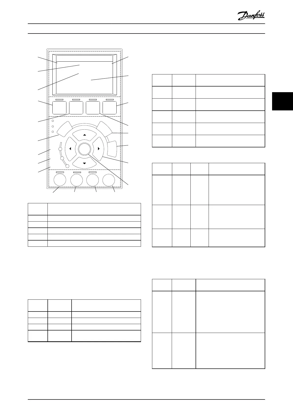
Callout
number
Description
1 AUX line voltage
2 Temperature power card
3 Actual UDC (current)
4 ISD power consumption
5 Actual UDC (voltage)
Illustration 4.2 Display Area when Connected to the SAB
B. Display menu keys
Menu keys are used to access menus for parameter set-up,
toggling through status display modes during normal
operation, and viewing fault log data.
Callout
number
Key Function
6 Status Shows operational information.
7 Quick Menu Allows access to parameters.
8 Main Menu Allows access to parameters.
9 Alarm Log Shows the last 10 alarms.
Table 4.1 Display Menu Keys
C. Navigation keys and indicator lights (LEDs)
Navigation keys are used to move the display cursor and
provide operation control in local operation. There are also
3 status LEDs in this area.
Callout
number
Key Function
10 Back Reverts to the previous step or list in
the menu structure.
11 Cancel Cancels the last change or command
(unless the display mode is changed).
12 Info Gives a denition of the current
function.
13 Navigation
keys
The 4 keys enable navigation between
menu items.
14 OK Accesses parameter groups or enables
a selection.
Table 4.2 Navigation Keys
Callout
number
LED Color Function
15 On Green The On LED activates when the
servo drive or SAB it is
connected to receives power
from the mains, auxiliary
supply, or a DC bus terminal.
16 Warn. Yellow When a warning is issued, the
yellow Warn. LED activates and
text appears in the display area
identifying the problem.
17 Alarm Red A fault condition causes the
red Alarm LED to ash and an
alarm text is shown.
Table 4.3 Indicator Lights (LEDs)
D. Operation keys and reset
The operation keys are at the bottom of the LCP.
Callout
number
Key Function
18 Hand On Enables the connected servo drive or
SAB to be controlled via the LCP. See
chapter 4.3.5 Hand On Mode for further
information.
Switching between Hand On mode and
Auto On mode is only possible in
certain states.
19 O Puts the SAB into state Standby and
the servo drive to state Switch on
Disabled.
This only works in Hand On mode.
O mode enables transition from Hand
On mode to Auto On mode.
Local Control Panel (LCP) O... Programming Guide
MG36D102 Danfoss A/S © 01/2017 All rights reserved. 95
4 4

 Loading...


