The [
▲
] and [
▼
] keys can be used to toggle between the
values shown in Readout 2 on Double-line readout or
Single-line readout.
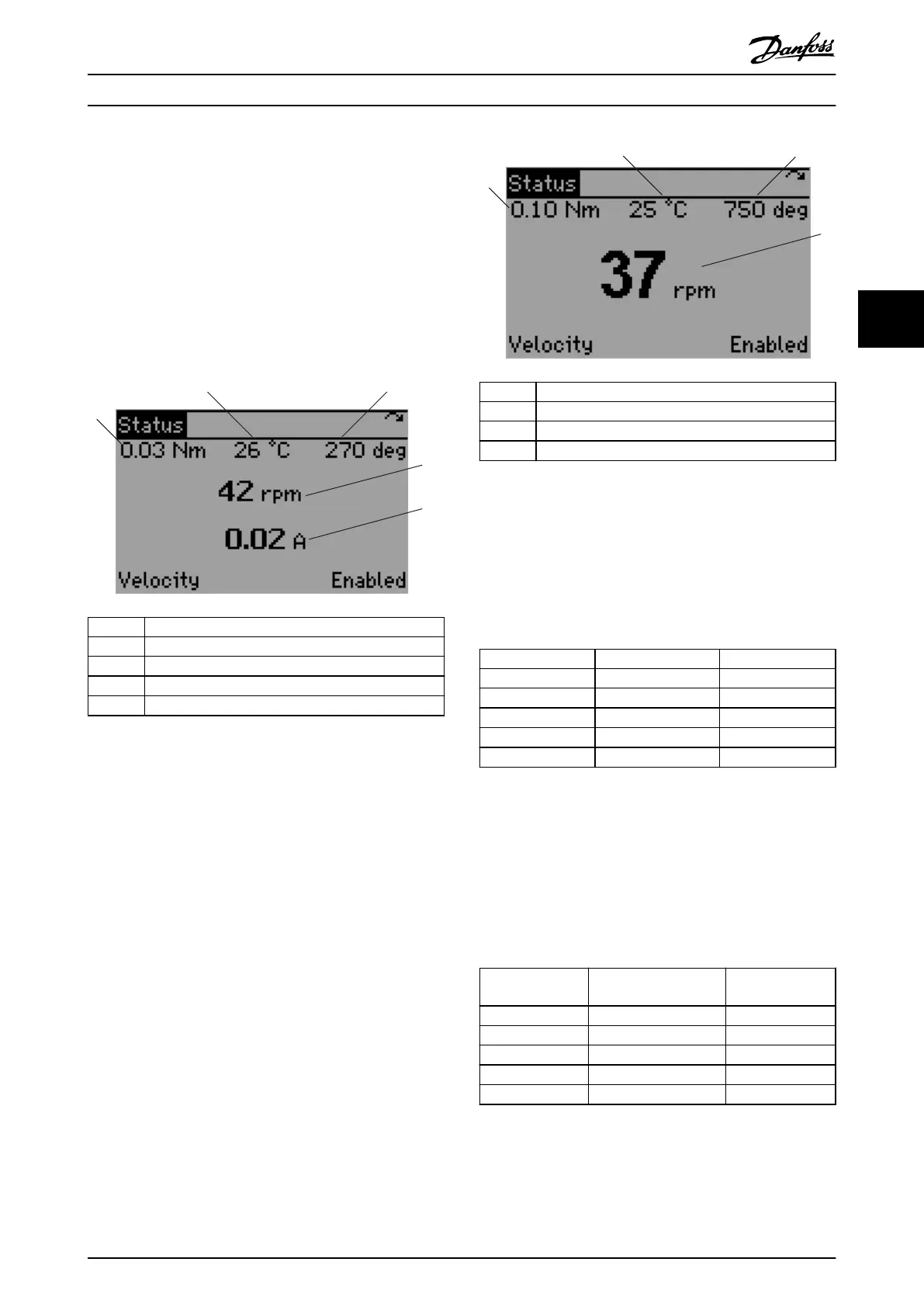
Double-line readout
This readout state is a default mode after start-up or initial-
ization. Use the [Info] key to obtain information about the
measurement links to the shown operating variables (1.1,
1.2, 1.3, 2, and 3). See the operating variables shown in
Illustration 4.4.
1 Readout 1.1
2 Readout 1.2
3 Readout 1.3
4 Readout 2
5 Readout 3
Illustration 4.4 Double-line Readout
Single-line readout
Use the [Info] key to obtain information about the
measurement links to the shown operating variables (1.1,
1.2, 1.3, and 2). See the operating variables shown in
Illustration 4.5. The dynamic data (readout parameters) on
the Status screen is updated 3 times per second.
1 Readout 1.1
2 Readout 1.2
3 Readout 1.3
4 Readout 2
Illustration 4.5 Single-line Readout
4.3.3.1 Default Readouts for ISD 510 Servo
Drive
The following parameters are the default readout congu-
ration:
Operating variable Name Parameter number
1.1 Torque [16-16]
1.2 Temperature module [16-34]
1.3 Drive position [16-20]
2 Speed [16-17]
3 Current actual value [16-14]
Table 4.7 Default Readouts for ISD 510 Servo Drive
The readout conguration can be changed and is retained
after a power cycle.
4.3.3.2 Default Readouts for SAB
The following parameters are the default readout congu-
ration:
Operating
variable
Name Parameter number
1.1 AUX line voltage [50-61]
1.2 Temperature power card [16-31]
1.3 Actual UDC (current) [50-73]
2 ISD power consumption [16-10]
3 Actual UDC (voltage) [16-30]
Table 4.8 Default Readouts for SAB
The readout
conguration can be changed and is retained
after a power cycle.
Local Control Panel (LCP) O... Programming Guide
MG36D102 Danfoss A/S © 01/2017 All rights reserved. 97
4 4

 Loading...


