Hardware Description 33
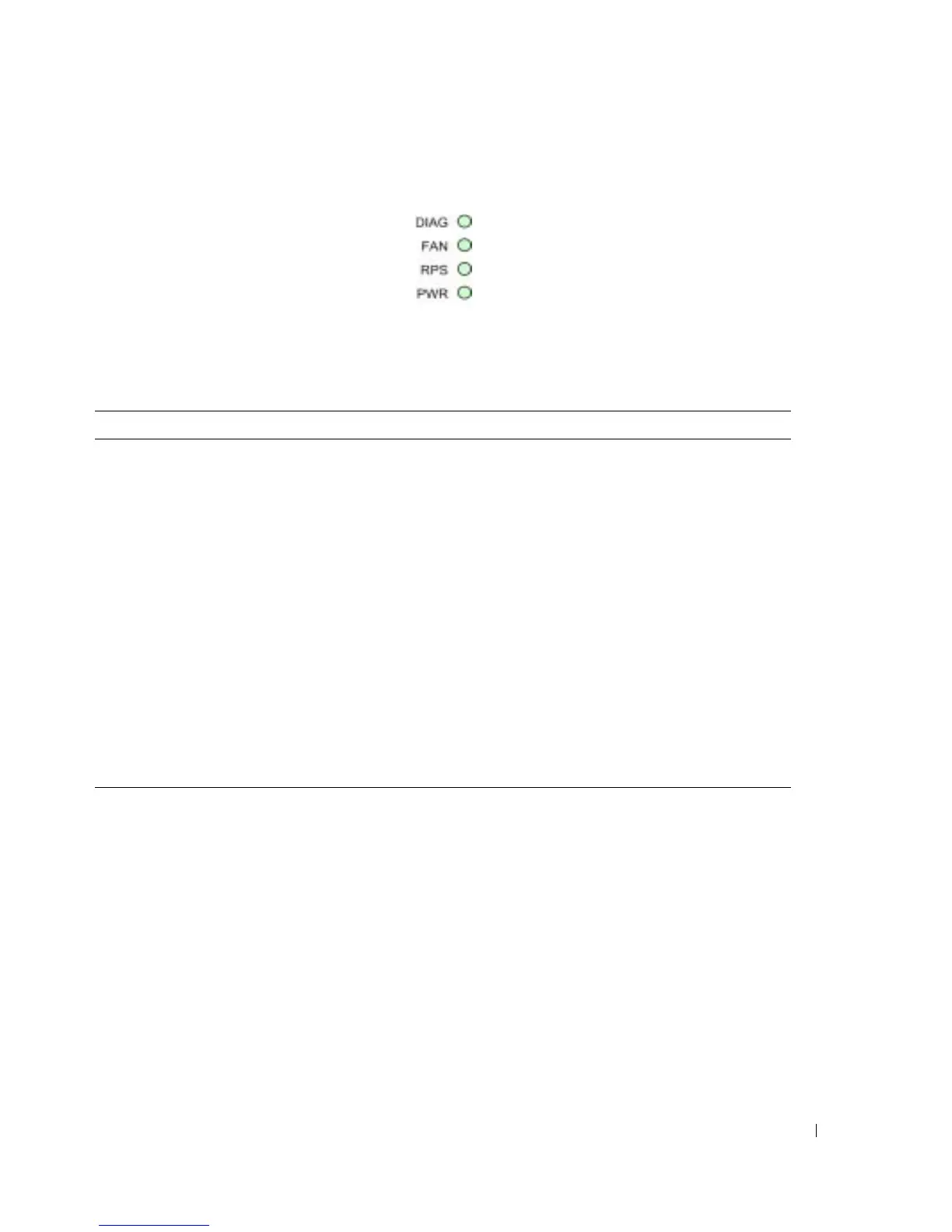
Figure 2-8. System LEDs
The following table describes the system LED indications.
Hardware Components
Power Supplies
The device has an internal power supply unit (AC unit) and a connector to connect the device to
an external power supply unit (DC unit). The external unit provides redundancy and is called an
RPS unit. To power up the device, only one power supply is required. Operation with both power
supply units is regulated through load sharing.
Load sharing is where the device power requirements are devided between the two power supplies.
If one power supply has an outage, the second power supply automatically continues providing
power to the whole device.
Table 2-3. System LED Indications
LED Color Description
Diagnostics (DIAG) Green Flashing The system is currently running a diagnostic test.
Green Static The system passed the diagnostic test.
Red Static The system failed the diagnostic test.
Fan (FAN) Green Static The device fans are operating normally.
Red Static One or more fans are not operating.
Redundant Power Supply (RPS) Green Static The redundant power supply is currently operating.
Red Static The redundant power supply is not operating.
OFF The redundant power supply is not currently
operating.
Main Power Supply (PWR) Green Static The main power supply is currently operating
normally.
OFF The main power supply is not currently operating.
Red The main power supply has failed
 Loading...