Electrical system
Connector blocks
Bravo-Brava
55.
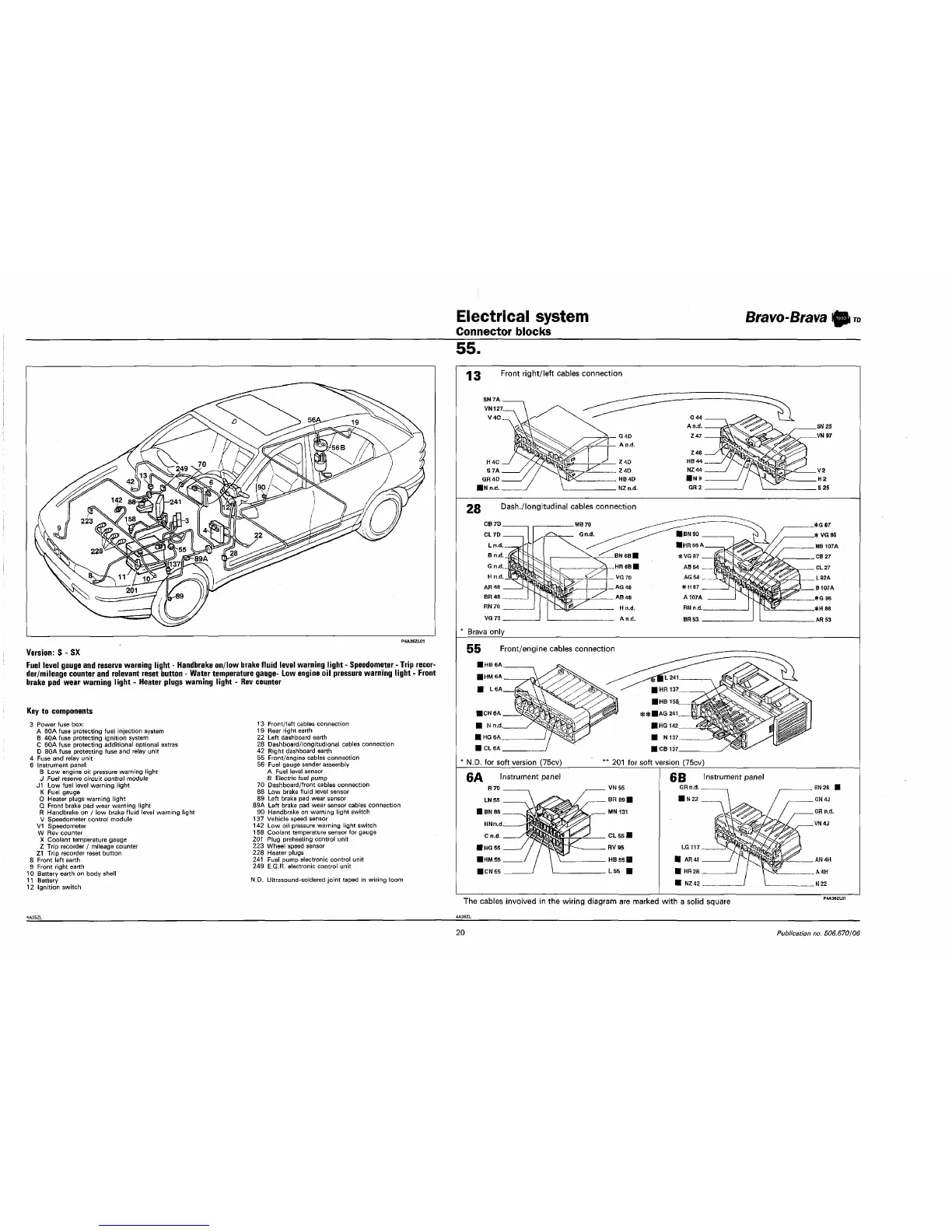
Version:
S - SX
Fuel level gauge and reserve warning light - Handbrake on/low brake fluid level warning light - Speedometer - Trip recor-
der/mileage counter and relevant reset button - Water temperature gauge- Low engine oil pressure warning light - Front
brake pad wear warning light - Heater plugs warning light - Rev counter
Key to components
3 Power fuse
box:
A 60A fuse protecting fuel injection system
B
40A
fuse protecting ignition system
C 60A fuse protecting additional optional extras
D 80A fuse protecting fuse and relay unit
4 Fuse and relay unit
6 Instrument panel;
B
Low
engine
oil
pressure warning light
J Fuel reserve circuit control module
J1 Low fuel level warning light
K Fuel gauge
0 Heater plugs warning light
Q Front brake pad wear warning light
R Handbrake
on / low
brake fluid level warning light
V Speedometer control module
V1 Speedometer
W Rev counter
X Coolant temperature gauge
Z Trip recorder
/
mileage counter
Z1 Trip recorder reset button
8 Front left earth
9 Front right earth
10 Battery earth
on
body shell
11 Battery
12 Ignition switch
13 Front/left cables connection
19 Rear right earth
22 Left dashboard earth
28 Dashboard/longitudional cables connection
42 Right dashboard earth
55 Front/engine cables connection
56 Fuel gauge sender assembly
A Fuel level sensor
B Electric fuel pump
70 Dashboard/front cables connection
88
Low
brake fluid level sensor
89 Left brake pad wear sensor
89A Left brake pad wear sensor cables connection
90 Handbrake
on
warning light switch
137 Vehicle speed sensor
142
Low oil
pressure warning light switch
158 Coolant temperature sensor
for
gauge
201 Plug preheating control unit
223 Wheel speed sensor
228 Heater plugs
241 Fuel pump electronic control unit
249 E.G.R. electronic control unit
N.D. Ultrasound-soldered joint taped
in
wiring loom
13
Front right/left cables connection
Dash./longitudinal cables connection
Brava only
Front/engine cables connection
N.D.
for
soft version (75cv) ' 201 for soft version (75cv)
(JB Instrument panel
GR n.d..
The cables involved
in
the wiring diagram are marked with a solid square
20
Publication
no.
506.670/06