Bravo-Brava Electrical system
Lighting
55.
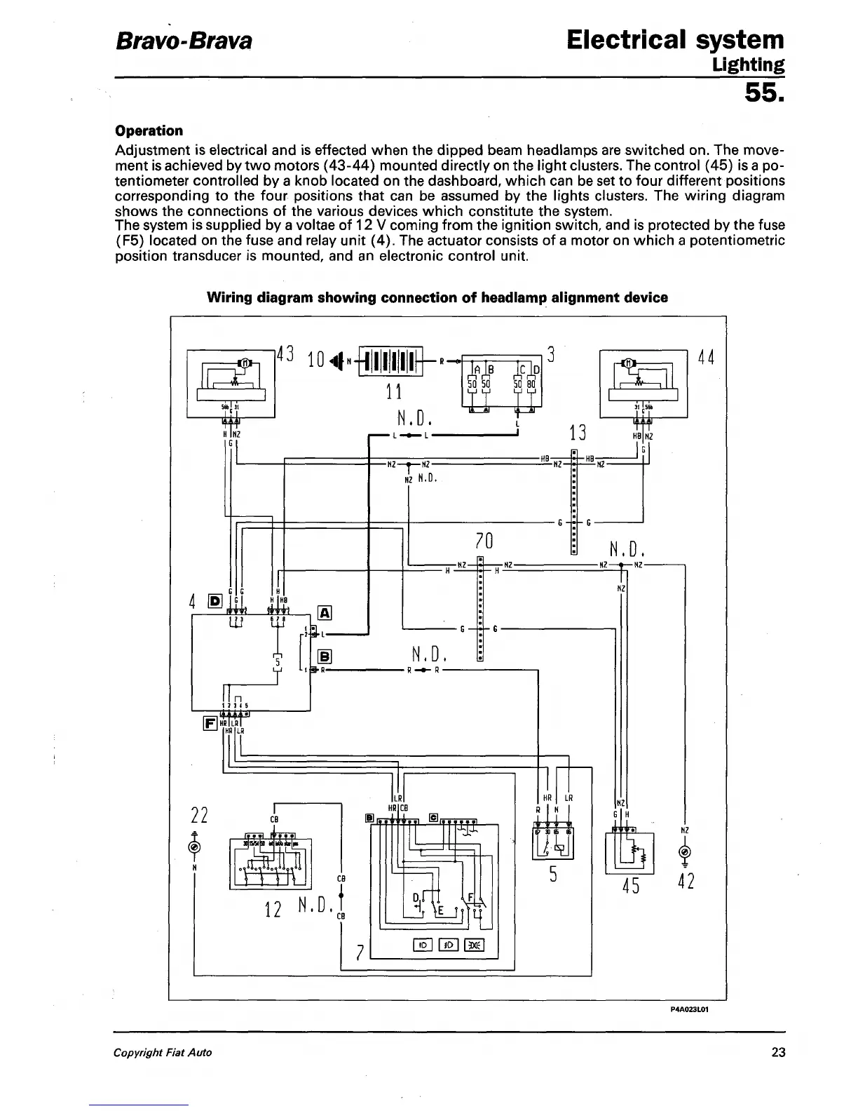
Operation
Adjustment is electrical and is effected when the dipped beam headlamps are switched on. The move-
ment is achieved by two motors (43-44) mounted directly on the light clusters. The control (45) is
a
po-
tentiometer controlled by a knob located on the dashboard, which can be set to four different positions
corresponding to the four positions that can be assumed by the lights clusters. The wiring diagram
shows the connections of the various devices which constitute the system.
The system is supplied by a voltae of 12 V coming from the ignition switch, and is protected by the fuse
(F5) located on the fuse and relay unit (4). The actuator consists of a motor on which a potentiometric
position transducer is mounted, and an electronic control unit.
Wiring diagram showing connection of headlamp alignment device
-™—i
43
io«f
N
TTTi
4 ®
in t
r
t
fU
y
■ii
m
hR—
[FIHRW
22
©
N
CB
»jia«p
Wfc
•R —»
CB
12
N
.D.t
CB
11
N.D.
50
50 50 80
i—m-
i—
m
1
-NZ—•— N2-
N2
N.D.
70
N.D.
■
R-»-
a
—
LR
HR
1 iMiyY
m
_jj \E_J
H
fiol Hoi facl
13
H8
-HB-
NZ-
■HB-
N.D.
-HZ | NZ-
NZ
G H
iiis.
h
44
45 «
Copyright Fiat Auto
23