Bravo-Brava
Electrical equipment
Recharging
55.
Voltage
(V)
Voltage
(V)
-40 -20 0 +20 +40 +60 +10
P4A113L06 °C
Electronic regulator ambient temperature
15
14,5
14
13,5-
13-
P4A113L03
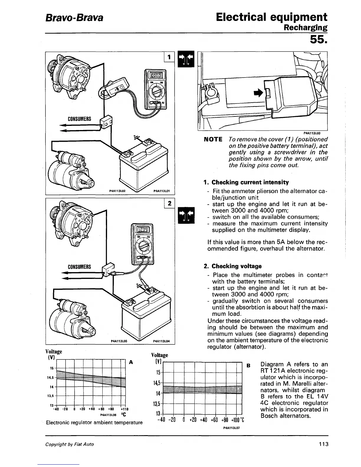
NOTE
To
remove the cover (1) (positioned
on the positive battery terminal), act
gently using a screwdriver in the
position shown by the arrow, until
the fixing pins come out.
1.
Checking current intensity
- Fit the ammeter plierson the alternator ca-
ble/junction unit
- start up the engine and let it run at be-
tween 3000 and 4000 rpm;
- switch on all the available consumers;
- measure the maximum current intensity
supplied on the multimeter display.
If this value is more than 5A below the rec-
ommended figure, overhaul the alternator.
2.
Checking voltage
- Place the multimeter probes in contact
with the battery terminals;
- start up the engine and let it run at be-
tween 3000 and 4000 rpm;
- gradually switch on several consumers
until the absorbtion is about half the maxi-
mum
load.
Under these circumstances the voltage
read-
ing should be between the maximum and
minimum values (see diagrams) depending
on the ambient temperature of the electronic
regulator (alternator).
-40 -20 0 +20 +40 +60 +80
+100 °C
P4A113L07
B Diagram A refers to an
RT 121A electronic
reg-
ulator which is incorpo-
rated in M. Marelli alter-
nators, whilst diagram
B refers to the EL 14V
4C electronic regulator
which is incorporated in
Bosch alternators.
Copyright by
Fiat
Auto 113