Bravo-Brava Electrical system
Fuse,
relay and control units
55.
"1
L_l
i 0
,=L
ii II ii
ii—r
FTi^|<=F9=»H=F1»ir~F10«||=F13=|
■
r
^n—nn—nn—nn—r
| «F14=.
ir^F15^1|
«F 5«=ll °F3 =
II
«T2
J
up
r,n—r;;
i
i '.rm.
F12^|=F4c=n|
B
F8=lFF7 = ||=F6 = l
1 r^l TT
Bl
14 5 4 9
ferity
i H—r
IS 8
A
IpsfeD^i
I 5-
rp—pa
!|==iyj===jj
J 7_
H 0_Q n n n n n
! ^
L.0J
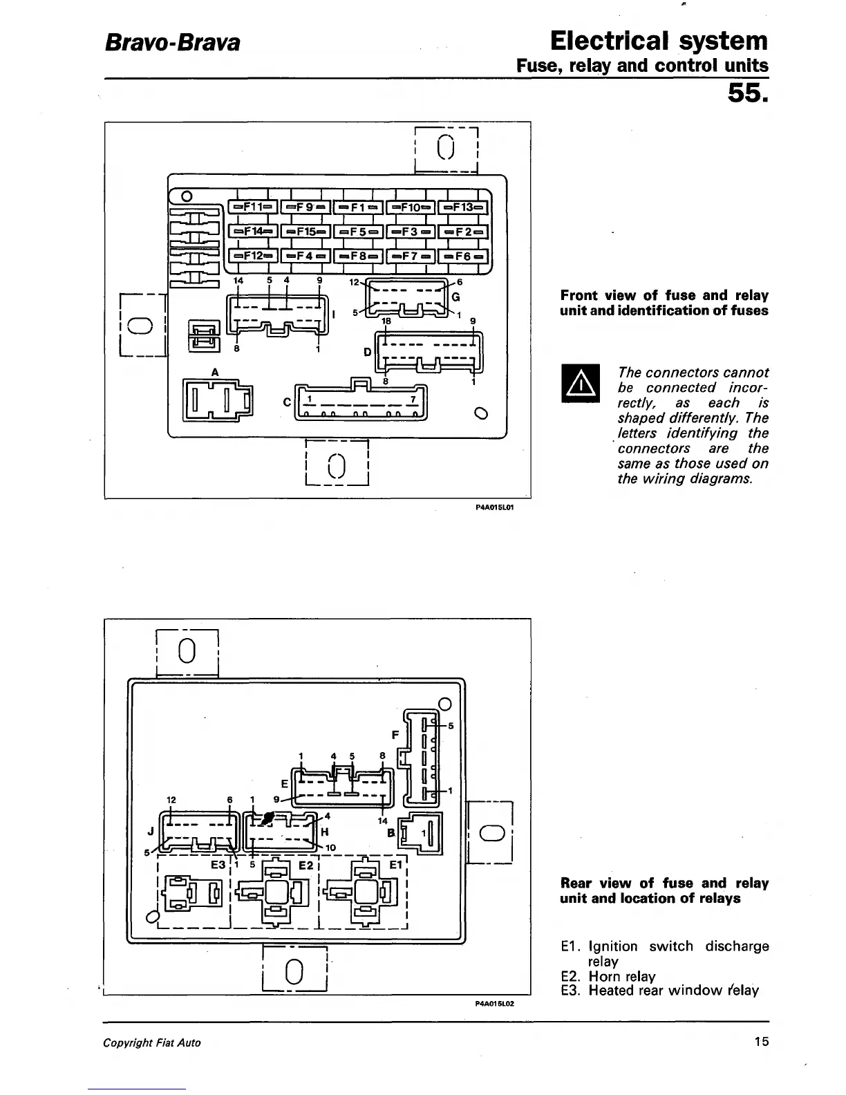
Front view of fuse and relay
unit and identification of fuses
The connectors cannot
be connected
incor-
rectly,
as each is
shaped differently. The
letters identifying the
connectors are the
same as those used on
the wiring diagrams.
L-
U
_J
LP_J
8
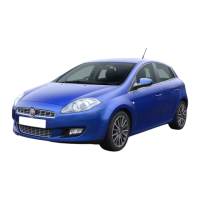
Rear view of fuse and relay
unit and location of relays
E1.
Ignition switch discharge
relay
E2.
Horn relay
E3.
Heated rear window relay
Copyright Fiat Auto
15