Electrical equipment
Instrument panel
Bravo-Brava
55.
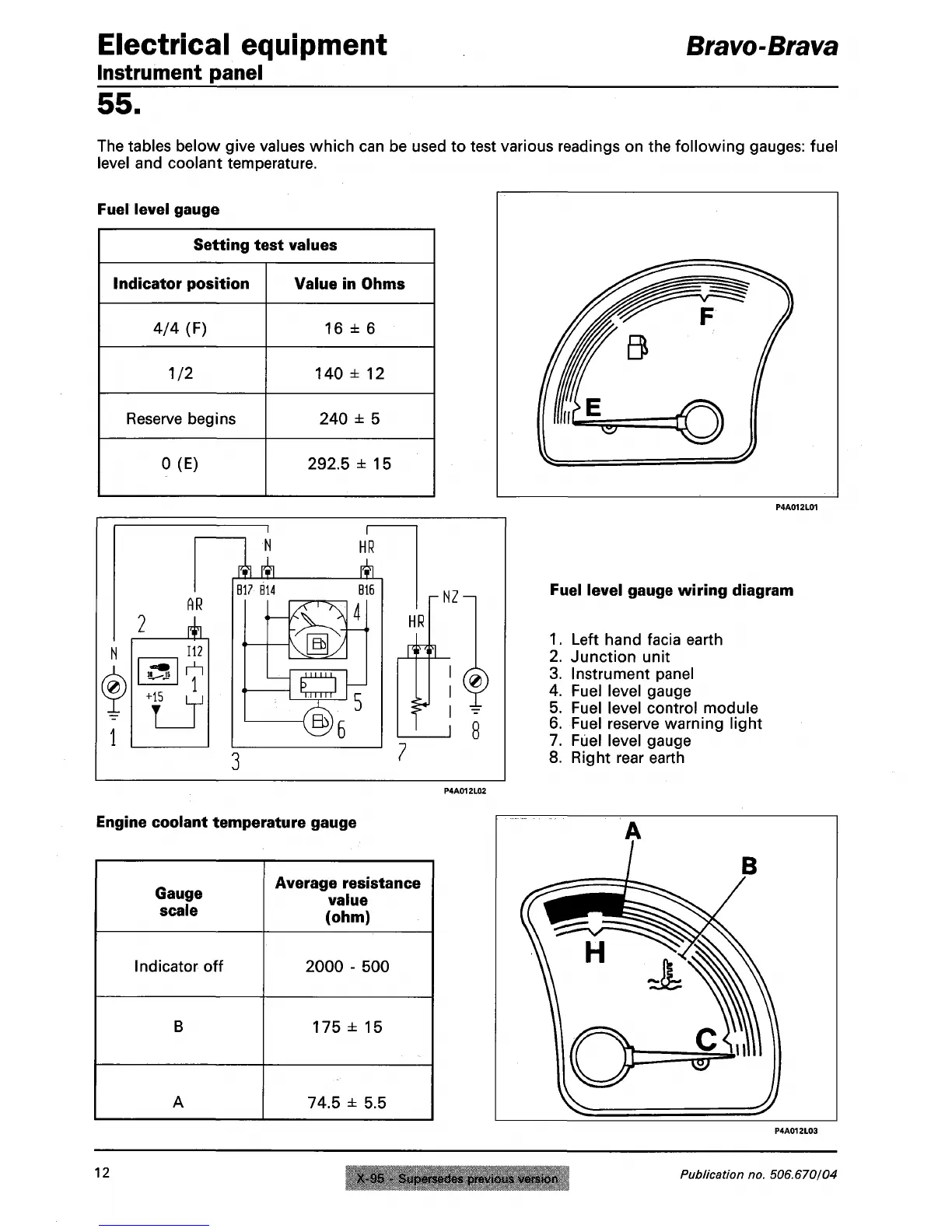
The tables below give values which can be used to test various readings on the following gauges: fuel
level and coolant temperature.
Fuel level gauge
Setting test values
Indicator position
4/4 (F)
1/2
Reserve begins
0(E)
Value in Ohms
16 ± 6
140 ± 12
240 ± 5
292.5 ±15
AR
it
112
1
+15 M
ffl P^
HR
A.
B17 B14
B16
rNZ^
HR
f
8
Fuel level gauge wiring diagram
1.
Left hand facia earth
2.
Junction unit
3. Instrument panel
4.
Fuel level gauge
5. Fuel level control module
6. Fuel reserve warning light
7. Fuel level gauge
8. Right rear earth
Engine coolant temperature gauge
Gauge
scale
Indicator off
B
A
Average resistance
value
(ohm)
2000 - 500
175 ± 15
74.5 ± 5.5
12
X-95 - Supersedes previous version
Publication no. 506.670/04