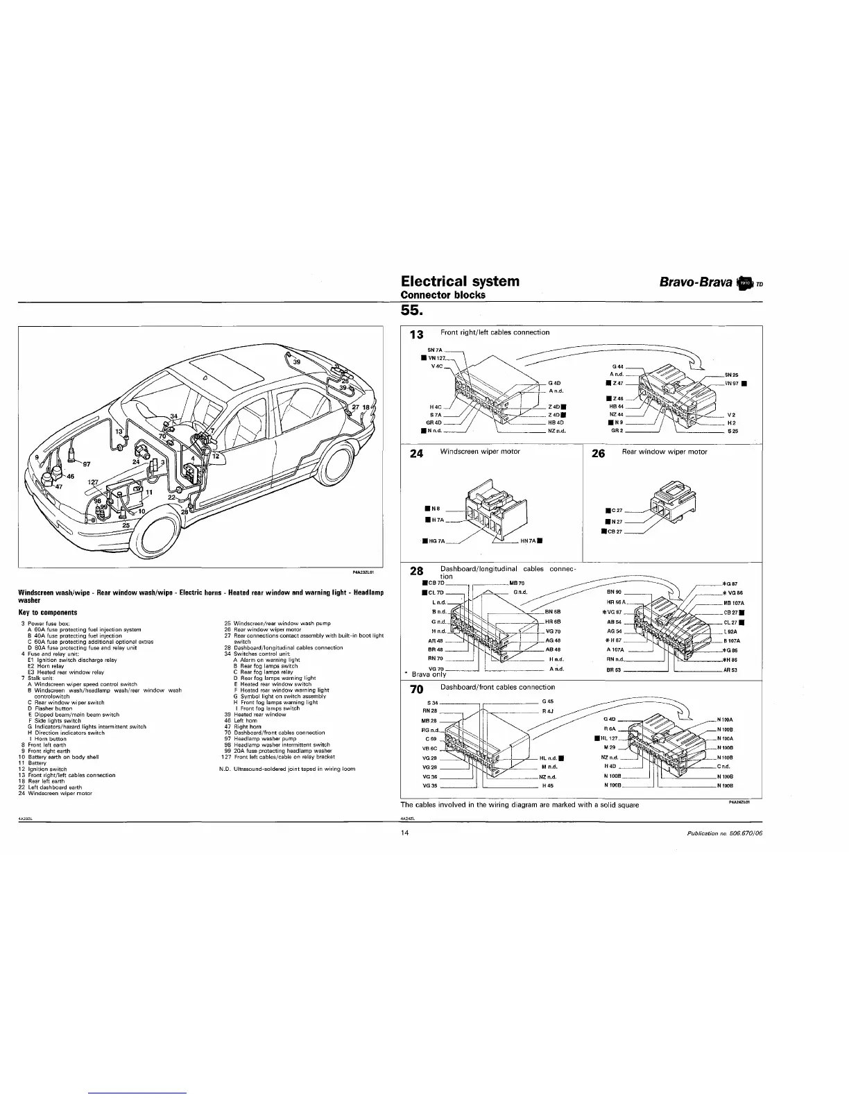
Electrical system
Connector blocks
Bravo-Brava
A
7
55.
Windscreen wash/wipe - Rear window wash/wipe - Electric horns - Heated rear window and warning light - Headlamp
washer
Key to components
3 Power fuse box:
A 60A fuse protecting fuel injection system
B 40A fuse protecting fuel injection
C 60A fuse protecting additional optional extras
D 80A fuse protecting fuse and relay unit
4 Fuse and relay unit:
E1 Ignition switch discharge relay
E2 Horn relay
E3 Heated rear window relay
7 Stalk unit:
A Windscreen wiper speed control switch
B Windscreen wash/headlamp wash/rear window wash
controlswitch
C Rear window wiper switch
D Flasher button
E Dipped beam/main beam switch
F Side lights switch
G Indicators/hazard lights intermittent switch
H Direction indicators switch
I Horn button
8 Front left earth
9 Front right earth
10 Battery earth on body shell
11 Battery
12 Ignition switch
13 Front right/left cables connection
18 Rear left earth
22 Left dashboard earth
24 Windscreen wiper motor
25 Windscreen/rear window wash pump
26 Rear window wiper motor
27 Rear connections contact assembly with built-in boot light
switch
28 Dashboard/longitudinal cables connection
34 Switches control unit:
A Alarm on warning light
B Rear fog lamps switch
C Rear fog lamps relay
D Rear fog lamps warning light
E Heated rear window switch
F Heated rear window warning light
G Symbol light on switch assembly
H Front fog lamps warning light
I Front fog lamps switch
39 Heated rear window
46 Left horn
47 Right horn
70 Dashboard/front cables connection
97 Headlamp washer pump
98 Headlamp washer intermittent switch
99 20A fuse protecting headlamp washer
127 Front left cables/cable on relay bracket
N.D. Ultrasound-soldered joint taped in wiring loom
Front right/left cables connection
24
Windscreen wiper motor
28
Dashboard/longitudinal cables connec
tion
ICB7D , , MB70
Brava only
Dashboard/front cables connection
The cables involved in the wiring diagram are marked with a solid square
14
Publication no. 506.670106