Electrical system
Connector blocks
Bravo-Brava
55.
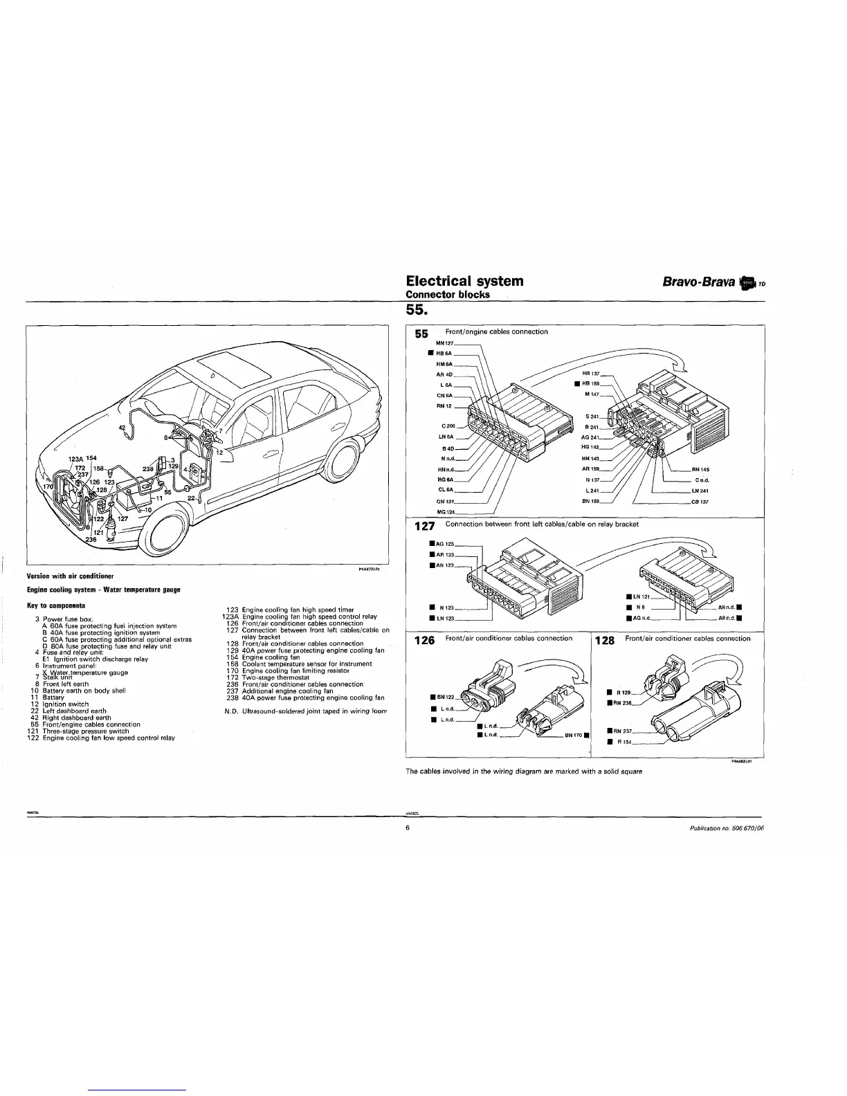
Version with air conditioner
Engine cooling system - Water temperature gauge
Key to components
3 Power fuse box;
A 60A fuse protecting fuel injection system
B 40A fuse protecting ignition system
C 60A fuse protecting additional optional extras
D 80A fuse protecting fuse and relay unit
4 Fuse and relay unit:
E1 Ignition switch discharge relay
6 Instrument panel:
7 Wu
e
nh
temperatUre gaU9e
8 Front left earth
10 Battery earth on body shell
11 Battery
12 Ignition switch
22 Left dashboard earth
42 Right dashboard earth
55 Front/engine cables connection
121 Three-stage pressure switch
122 Engine cooling fan low speed control relay
123 Engine cooling fan high speed timer
123A Engine cooling fan high speed control relay
126 Front/air conditioner cables connection
127 Connection between front left cables/cable on
relay bracket
128 Front/air conditioner cables connection
129 40A power fuse protecting engine cooling fan
154 Engine cooling fan
158 Coolant temperature sensor for instrument
170 Engine cooling fan limiting resistor
172 Two-stage thermostat
236 Front/air conditioner cables connection
237 Additional engine cooling fan
238 40A power fuse protecting engine cooling fan
N.D. Ultrasound-soldered joint taped in wiring loom
EC Front/engine cables connection
MN127
■ HB6A
HM6A
AH 4D
L6A
CN6A
RN12
1 97 Connection between front left cables/cable on relay bracket
I N123
I LN123.
ANn.d.l
ARn.d.l
1 26 Front/air conditioner cables connection
1 28 Front/air conditioner cables connection
I R129
IHN
238.
The cables involved in the wiring diagram are marked with a solid square
6
Publication no. 506.670/06