Electrical system
Connections
Bravo-Brava
®
'98 range
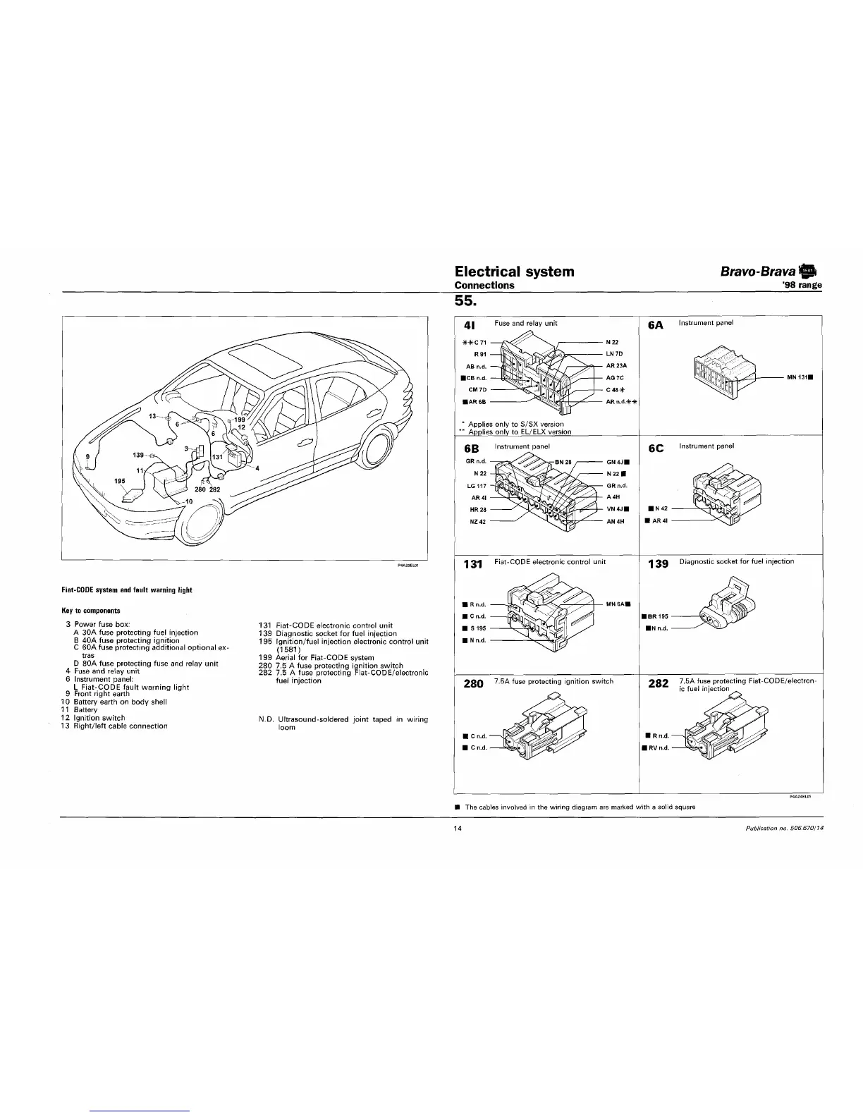
Fiat-COOE system and fault warning light
Key to components
3 Power fuse box:
A 30A fuse protecting fuel injection
B 40A fuse protecting ignition
C 60A fuse protecting additional optional ex-
tras
D 80A fuse protecting fuse and relay unit
4 Fuse and relay unit
6 Instrument panel:
L Fiat-CODE fault warning light
9 Front right earth
10 Battery earth on body shell
11 Battery
12 Ignition switch
13 Right/left cable connection
131 Fiat-CODE electronic control unit
139 Diagnostic socket for fuel injection
195 Ignition/fuel injection electronic control unit
(1581)
199 Aerial for Fiat-CODE system
280 7.5 A fuse protecting ignition switch
282 7.5 A fuse protecting Fiat-CODE/electronic
fuel injection
N.D. Ultrasound-soldered joint taped in wiring
loom
55.
Fuse and relay unit
Applies only to S/SX version
Applies only to EL/ELX version
131
Fiat-CODE electronic control unit
-=H—
MN6AI
280 7.5A
f
uge
protecting ignition switch
£A Instrument panel
BC Instrument panel
1 39 Diagnostic socket for fuel injection
282 7.5A '
use
protecting Fiat-CODE/electron-
ic fuel injection
The cables involved in the wiring diagram are marked with a solid square
14
Publication no. 506.670/14