Electrical system
Connections
Bravo-Brava
'98 range
55.
P4A27EL01
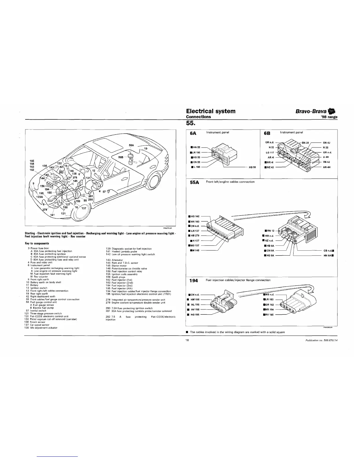
Starting - Electronic ignition and fuel injection - Recharging and warning light - Low engine oil pressure warning light -
Fuel injection fault warning light - Rev counter
Key to components
3 Power fuse box:
A 30A fuse protecting fuel injection
B 40A fuse protecting ignition
C 60A fuse protecting additional optional extras
D 80A fuse protectiing fuse and relay unit
4 Fuse and relay unit
6 Instrument panel:
A Low generator recharging warning light
B Low engine
oil
pressure warning light
M Fuel injection fault warning light
W Rev counter
9 Front right earth
10 Battery earth
on
body shell
11 Battery
1
2 Ignition switch
13 Front right/left cables connection
19 Rear right earth
42 Right dashboard earth
55 Front cables/fuel gauge control connection
56 Fuel gauge control unit
A Fuel gauge sensor
B Electric fuel pump
57 Inertial switch
121 Three-stage pressure switch
131 Fiat-CODE electronic control unit
132 Petrol vapours cut-off solenoid (canister)
136 Knock sensor
1
37 Car speed sensor
138 Idle adjustment actuator
139 Diagnostic socket
for
fuel injection
141 Heated Lambda probe
142 Low
oil
pressure warning light switch
143 Alternator
144 Rpm and T.D.C. sensor
145 Starter motor
146 Potentiometer on throttle valve
150 Fuel injection control relay
155 Ignition coils assembly
156 Spark plugs
162 Fuel injector
(1st)
163 Fuel injector (2nd)
1
64 Fuel injector
(3rd)
165 Fuel injector
(4th)
1
94 Fuel injection cables/fuel injector flange connection
195 Ignition/fuel injection electronic control unit (15S1)
278 Integrated
air
temperature/pressure sender unit
279 Engine coolant temperature double sender unit
280 7.5A fuse protecting ignition switch
281 30A fuse protecting Lambda probe/canister solenoid
282
7.5
injection
fuse protecting Fiat-CQDE/electronic
CA Instrument panel
194
6B
Instrument panel
55A Front left/engine cables connection
Fuel injection cables/injector flange connection
P4A2BEL01
The cables involved in the wiring diagram are marked with a solid square
16
Publication no. 506.670/74