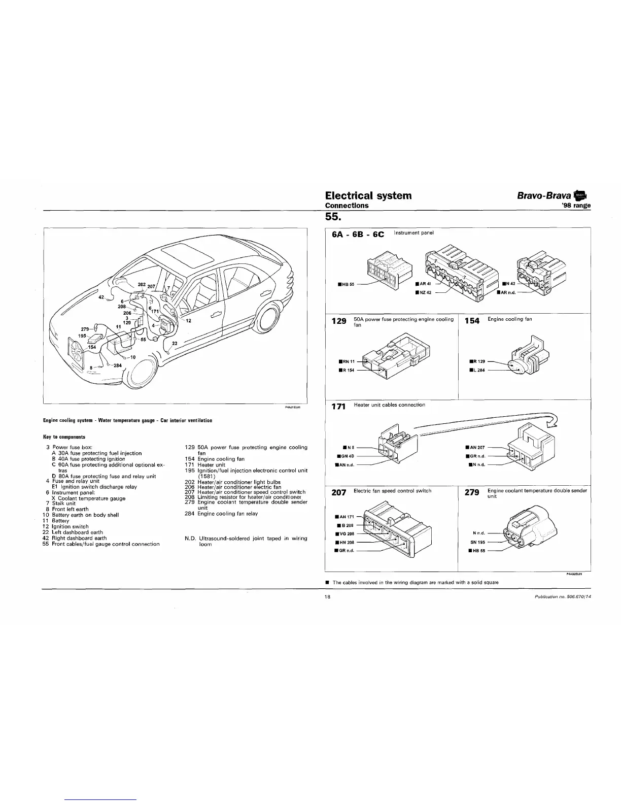
Electrical system
Connections
Bravo-Brava
'98 range
55.
Engine cooling system - Water temperature gauge - Car interior ventilation
Key to components
3 Power fuse box:
A 30A fuse protecting fuel injection
B 40A fuse protecting ignition
C 60Afuse protecting additional optional ex-
tras
D 80A fuse protecting fuse and relay unit
4 Fuse and relay unit
E1 Ignition switch discharge relay
6 Instrument panel:
X Coolant temperature gauge
7 Stalk unit
8 Front left earth
10 Battery earth on body shell
11 Battery
12 Ignition switch
22 Left dashboard earth
42 Right dashboard earth
55 Front cables/fuel gauge control connection
129 50A power fuse protecting engine cooling
fan
154 Engine cooling fan
1 71 Heater unit
195 Ignition/fuel injection electronic control unit
(1581)
202 Heater/air conditioner light bulbs
206 Heater/air conditioner electric fan
207 Heater/air conditioner speed control switch
208 Limiting resistor for heater/air conditioner
279 Engine coolant temperature double sender
unit
284 Engine cooling fan relay
N.D. Ultrasound-soldered joint taped in wiring
loom
CA CD er Instrument panel
1 29 ^^ power fuse protecting engine cooling
fan
1 CA Engine cooling fan
171
Heater unit cables connection
207 Electric fan speed control switch
07Q Engine coolant temperature double sender
*
#3
unit
The cables involved in the wiring diagram are marked with a solid square
18
Publication no. 506.670/74