SECTION 6 - GENERAL MECHANICAL OVERHAUL
81
CURSOR SERIES
Print P4D32C006 E Base - 03/2015
Figure 196
α
221105
Perform the following if the conditions stated have not been
obtained:
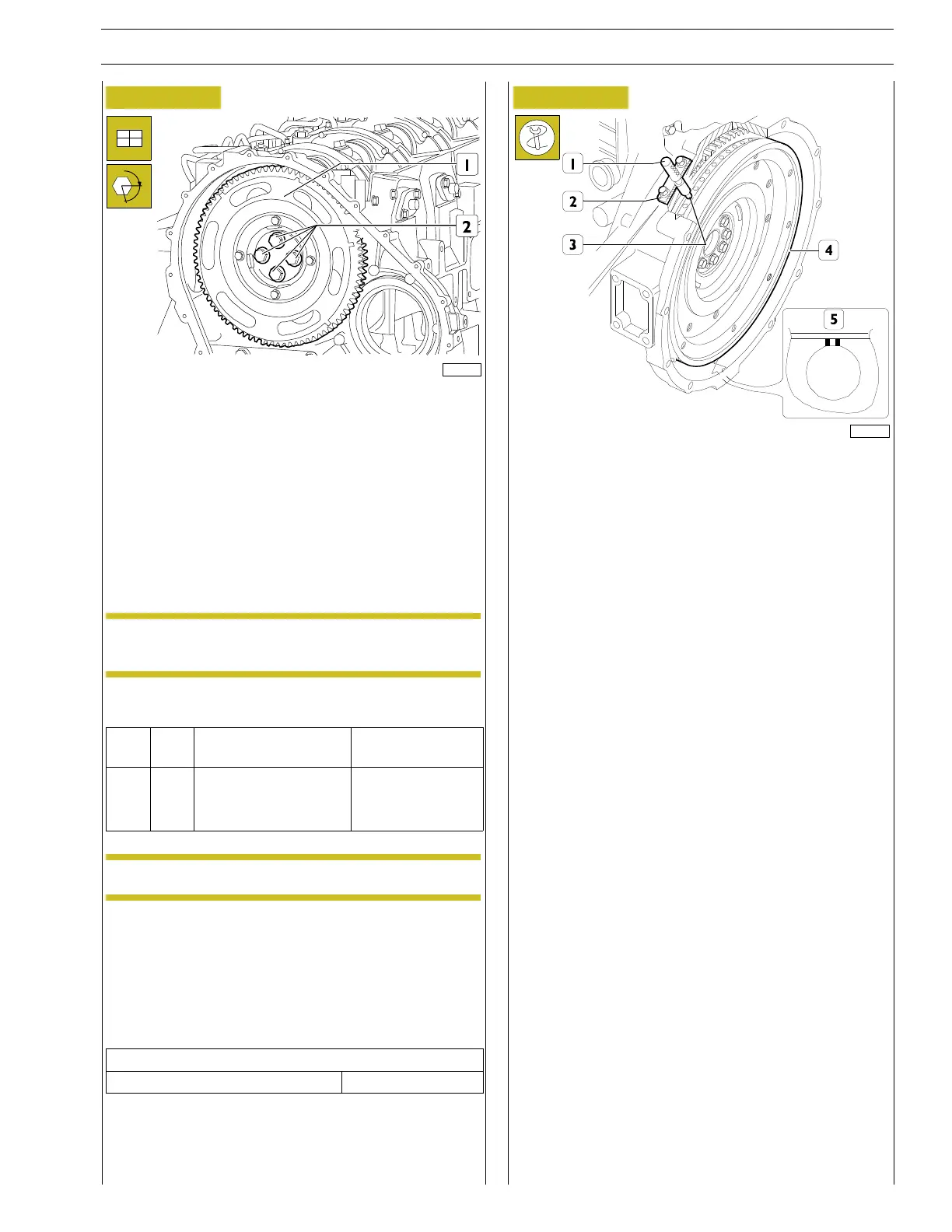
Turn the engine flywheel until the required cam lift value ap-
pears on the dial gauge.
Loosen the screws (2) that fasten the gear (1) to the camshaft
and use the slots on the gear (1).
Act on the engine flywheel to obtain the conditions indicated
while keeping the cam lift value unchanged.
Lock the screws (2) and repeat timing check as described
above.
NOTE While performing this operation recover the
clearance between the camshaft gears.
Tighten the screws (2) to the torque specified in the table.
Ref.
No. Description
Tightening
torques
(2) 4
ScrewsM14X4X60
Step 1 60 ± 3 Nm
Step 2 60˚
NOTE Lubricate the screws with engine oil.
When adjustment via the slots is not sufficient for recovering
the offset, proceed as follows:
Lock the screws (2) and turn the engine flywheel a 1/2 turn in
the opposite direction of the operating direction.
Turn the engine flywheel in the engine operating direction until
the dial gauge indicates the required camshaft lift value.
Technical data
Cam timing dial gauge value 5.95 ± 0.05 mm
Remove the screws (2) and disassemble the camshaft gear (1).
Figure 197
185523
Turn the flywheel (4) again until it reaches the following condi-
tions:
- The hole with two notches (5) is visible through the small
inspection window.
- The tool 99360612 (1), through the seat (2) of the engine
speed sensor , enters the hole (3) in the engine flywheel
(4).