80
SECTION 6 - GENERAL MECHANICAL OVERHAUL
CURSOR SERIES
Base - 03/2015 Print P4D32C006 E
Figure 194
185524
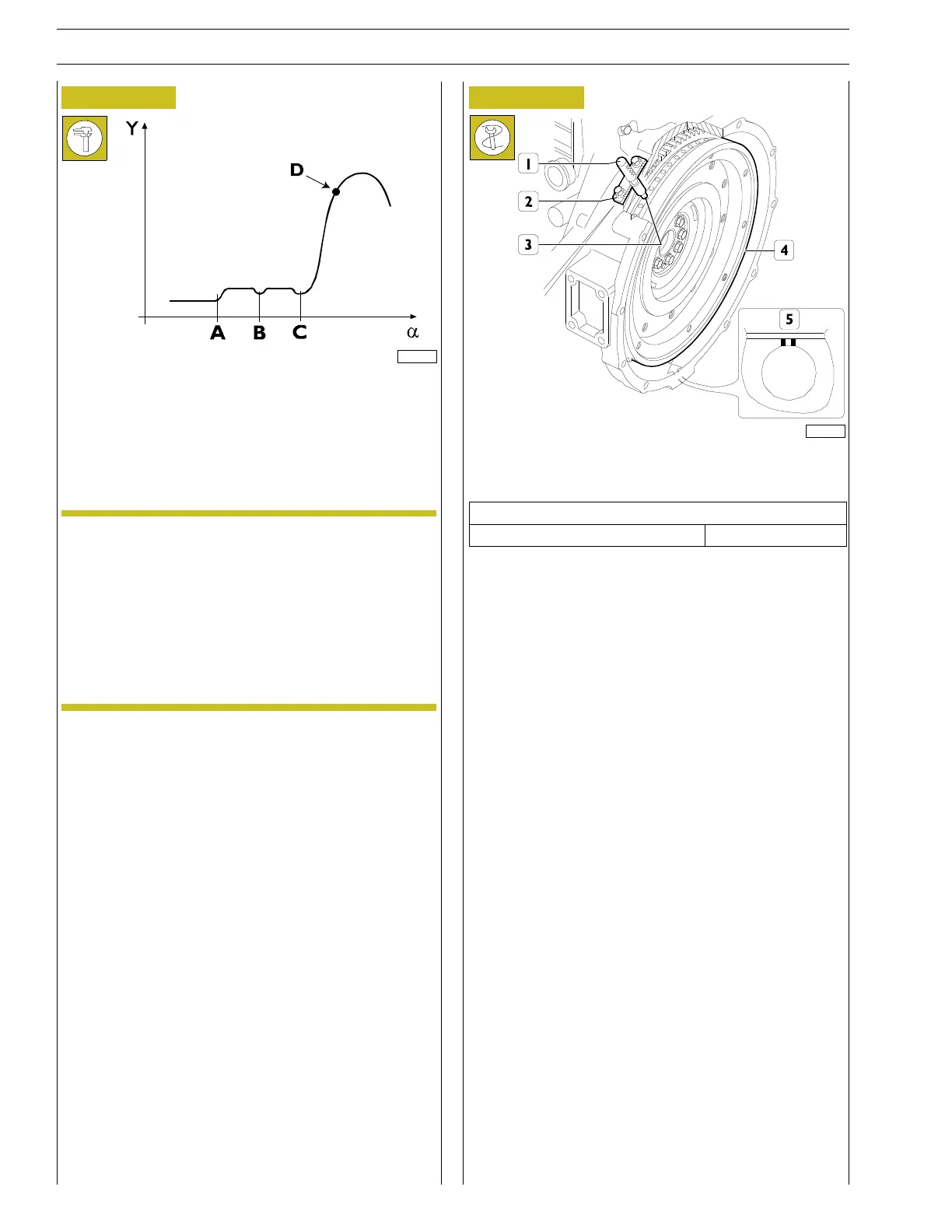
Camshaft rotation angle
Y Cam lift based on the rotation angle of the camshaft
D Cam lift in correspondence of the 54˚ before the top
dead centre , 1st cylinder end of compression
Reset the dial gauge first in point A.
NOTE The dial gauge is to be zeroed with the rocker arm
roller in contact with the base radius of the cam
profile .
For this, turn the flywheel until it exceeds protru-
sions (A-B) and (B-C) on the cam profile connec-
ted to the engine brake operation.
This condition occurs when the flywheel is turned
in the opposite direction of the operating direction
by approx. 1 and 1/4 rotations.
Figure 195
185523
Turn the engine flywheel in the engine operating direction until
the dial gauge indicates the required camshaft lift value.
Technical data
Cam timing dial gauge value 5.95 ± 0.05 mm
Check that the required cam lift values are displayed under the
following conditions:
- Theholewithtwonotches(5)isvisiblethroughthesmall
inspection window.
- The tool 99360612 (1), through the seat (2) of the engine
speed sensor , enters the hole (3) in the engine flywheel
(4).