Operation Manual - Security
Quidway S3500 Series Ethernet Switches Chapter 2 Portal Configuration
Huawei Technologies Proprietary
2-7
z After passing the Portal authentication, the user PC can access the Internet.
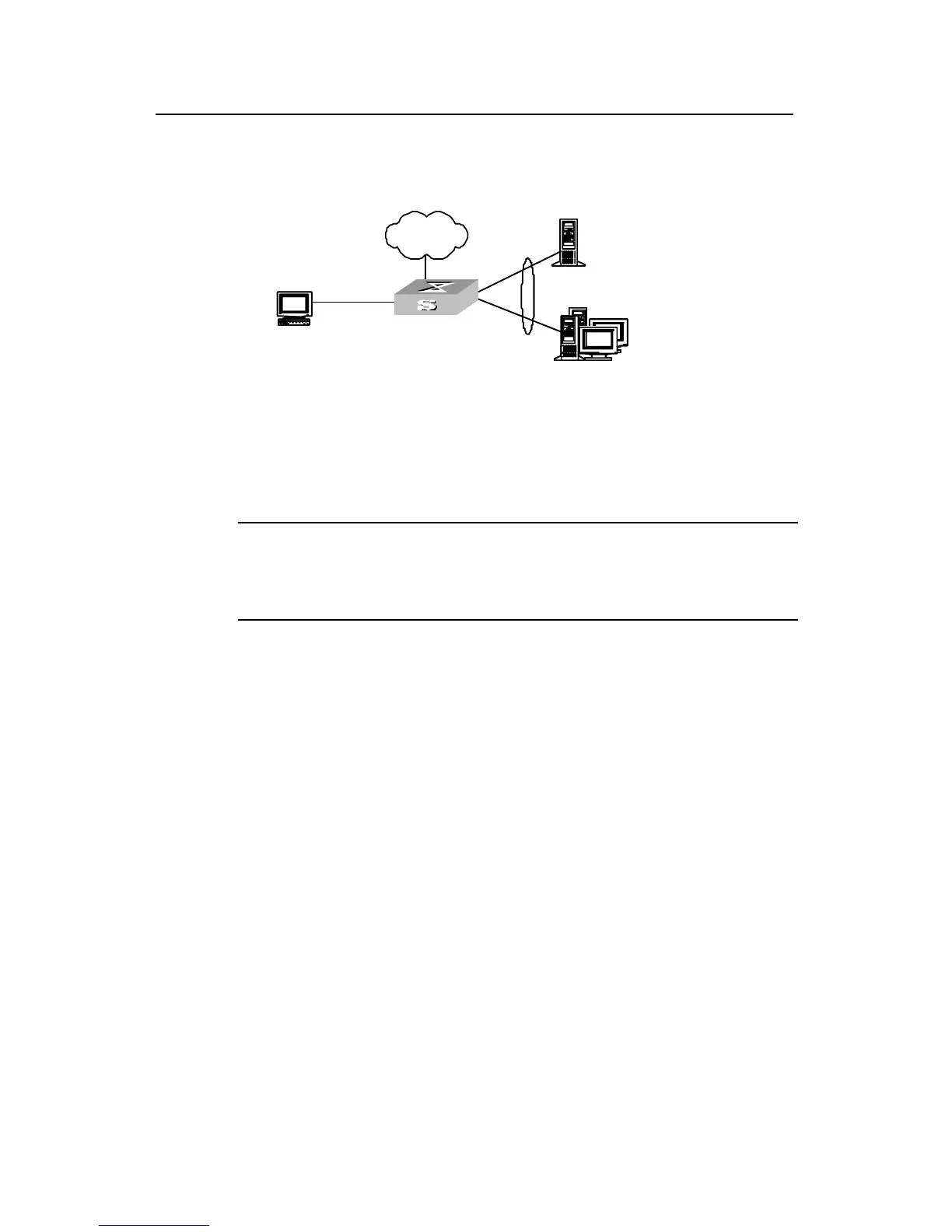
II. Network diagram
Switch
User PC
Portal serv er
RADIUS authentication/accounting serv er
v lan-interf ace 3
172.21.1.1/16
v lan-interf ace 2
192.168.1.160/16
Ethernet0/1
192.168.1.100/16
Ethernet0/3
Ethernet0/2
192.168.1.200/16
Gateway address: 172.21.1.1
172.21.1.2/16
VLAN 2
Internet
Ethernet0/10
Switch
User PC
Portal serv er
RADIUS authentication/accounting serv er
v lan-interf ace 3
172.21.1.1/16
v lan-interf ace 2
192.168.1.160/16
Ethernet0/1
192.168.1.100/16
Ethernet0/3
Ethernet0/2
192.168.1.200/16
Gateway address: 172.21.1.1
172.21.1.2/16
VLAN 2
Internet
Ethernet0/10
Figure 2-2 Network diagram for Portal direct authentication
III. Configuration procedure
Note:
The following describes the configurations of the switch. The configurations of the
Portal server and RADIUS authentication/accounting server are not described here.
1) Configure a RADIUS scheme
# Create a RADIUS scheme named portal.
[Quidway] radius scheme portal
# Configure the server type of the RADIUS scheme as Portal.
[Quidway-radius-portal] server-type portal
# Configure the primary authentication, primary accounting server, and communication
key for the RADIUS scheme.
[Quidway-radius-portal] primary authentication 192.168.1.100
[Quidway-radius-portal] primary accounting 192.168.1.100
[Quidway-radius-portal] key accounting hello
[Quidway-radius-portal] key authentication hello
[Quidway-radius-portal] user-name-format without-domain
[Quidway-radius-portal] quit
2) Configure ISP domain
# Create an ISP domain named portal.
[Quidway] domain portal
 Loading...


