Operation Manual - Routing Protocol
Quidway S3500 Series Ethernet Switches Chapter 5 BGP Configuration
Huawei Technologies Proprietary
5-29
5.4.3 Configuring BGP Routing
I. Networking requirements
This example illustrates how the administrators manage the routing via BGP attributes.
All Ethernet switches are configured with BGP, and IGP in AS 200 utilizes OSPF.
Switch A is in AS 100, and acts as Switch B of AS 200 and BGP neighbor of Switch C.
Switch B, Switch C and Switch D operate IBGP. Switch D is also in AS 200.
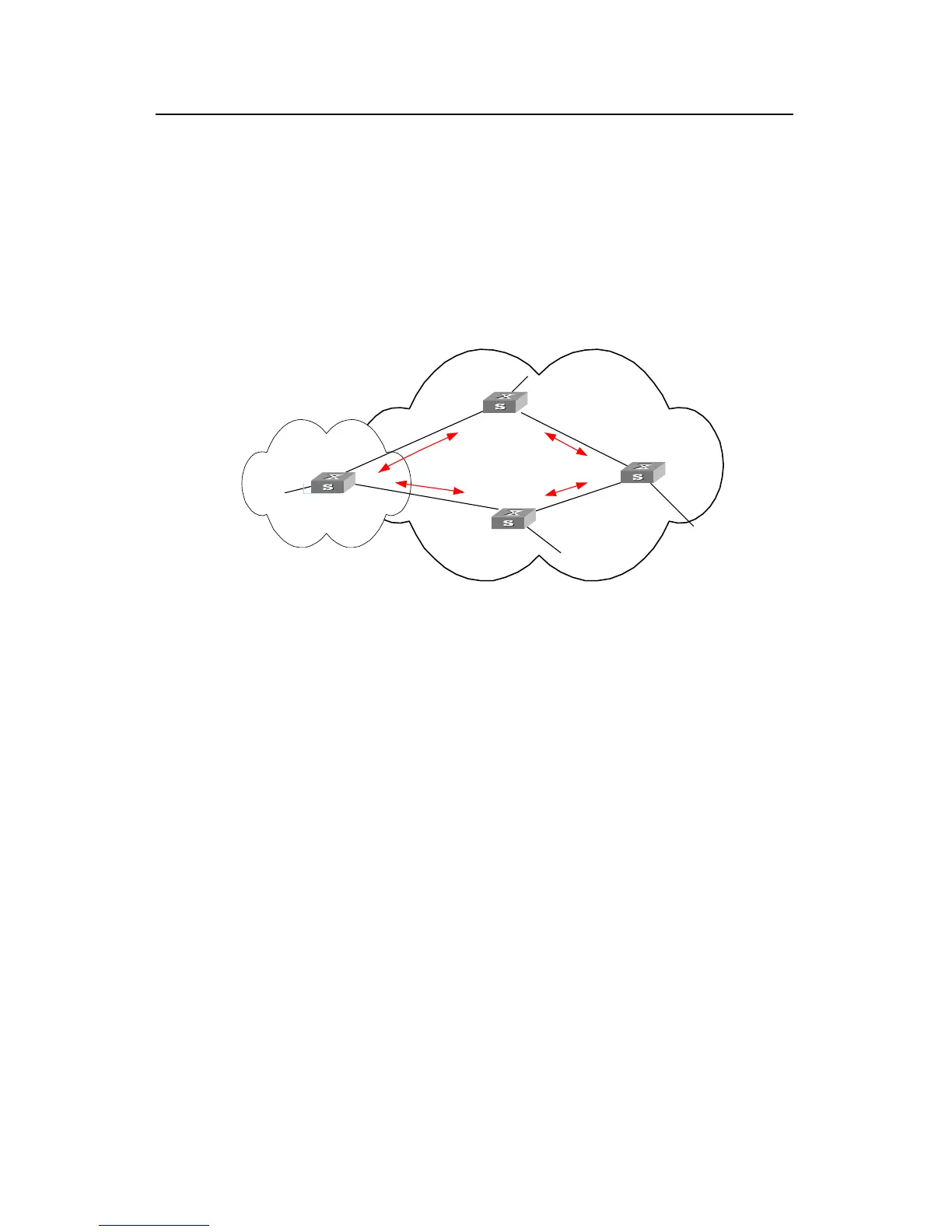
II. Networking diagram
VLAN 4
194.1.1.2/24
VLAN 2
192.1.1.1/24
VLAN 3
193.1.1.1/24
VLAN 3
193.1.1.2/24
VLAN 5
195.1.1.2/24
VLAN 2
192.1.1.2/24
2.2.2.2
4.4.4.4
3.3.3.3
1.1.1.1
AS100
AS200
VLAN 4
194.1.1.1/24
VLAN 5
195.1.1.1/24
IBGP
IBGP
EBGP
EBGP
To network
1.0.0.0
To network
2.0.0.0
To network
4.0.0.0
To network
3.0.0.0
Switch A
Switch B
Switch C
Switch D
Figure 5-4 Networking diagram of configuring BGP routing
III. Configuration procedure
1) Configure Switch A:
[Switch A] interface Vlan-interface 2
[Switch A-Vlan-interface2] ip address 192.1.1.1 255.255.255.0
[Switch A] interface Vlan-interface 3
[Switch A-Vlan-interface3] ip address 193.1.1.1 255.255.255.0
# Enable BGP
[Switch A] bgp 100
# Specify the network that BGP sends to
[Switch A-bgp] network 1.0.0.0
# Configure the peers
[Switch A-bgp] peer 192.1.1.2 as-number 200
[Switch A-bgp] peer 193.1.1.2 as-number 200
[Switch A-bgp] quit
# Configure the MED attribute of Switch A
z Add ACL on Switch A, enable network 1.0.0.0.
 Loading...


