Operation Manual - Auto Detecting
Quidway S3500 Series Ethernet Switches Chapter 2 Implementations of Auto Detect
Huawei Technologies Proprietary
2-4
Note:
z The prompts of interface views vary with the actual configurations.
z Refer to corresponding command manual for information about parameters listed in
the above table and the related undo commands.
2.3.2 Implementation Example
I. Network requirements
z Switch B and switch D form a VRRP backup group numbered 1, whose virtual IP
address is 192.168.1.10.
z Data sourced from Switch A and destined for Switch C is transmitted through
Switch B under normal situations.
z When the connection between switch B and switch C fails, switch D becomes the
Master in backup group 1 automatically and the link from Switch D to Switch C, the
secondary link, is enabled. Network diagram
192.168.1.2
20.1.1.2
10.1.1.3
10.1.1.4
Switch C
192.168.1.1/24
192.168.1.2/24
192.168.1.3/24
20.1.1.3/24
10.1.1.3/24
Ethernet 1/0/1
10.1.1.4/24
Ethernet 2/0/1
Switch A
Switch B
Switch C
Switch D
VLAN 1
20.1.1.4/24
VLAN 1
VLAN 1
VLAN 1
192.168.1.2
20.1.1.2
10.1.1.3
10.1.1.4
Switch C
192.168.1.1/24
192.168.1.2/24
192.168.1.3/24
20.1.1.3/24
10.1.1.3/24
Ethernet 1/0/1
10.1.1.4/24
Ethernet 2/0/1
Switch A
Switch B
Switch C
Switch D
VLAN 1
20.1.1.4/24
VLAN 1
VLAN 1
VLAN 1
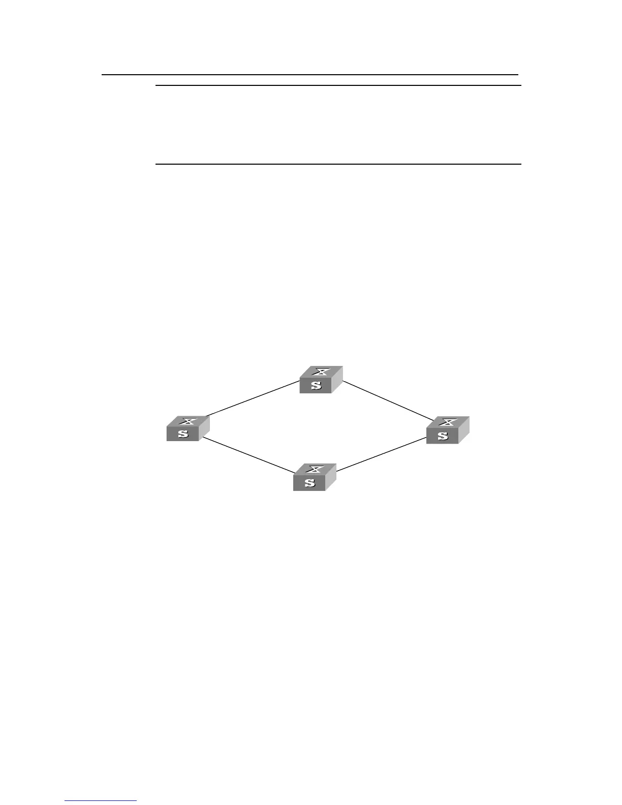
Figure 2-2 Network diagram for VRRP
II. Configuration procedure
1) Configure Switch B as the following:
# Enter system view.
<Quidway B> system-view
# Create a detecting group numbered 9.
[Quidway B] detect-group 9
# Specify to detect the reachability to the interface with an IP address of 10.1.1.4, and
set the detect number to 1.
[Quidway B-detect-group-9] detect-list 1 ip address 10.1.1.4
[Quidway B-detect-group-9] quit
 Loading...


