Operation Manual - Security
Quidway S3500 Series Ethernet Switches Chapter 2 Portal Configuration
Huawei Technologies Proprietary
2-10
# Configure DHCP Relay.
[Quidway-Vlan-interface3] dhcp select relay
[Quidway-Vlan-interface3] ip relay address 192.168.1.100
# Enable Portal authentication on VLAN interface 3. The Portal server name is newp,
and you can refer to section 2.2.3 “Portal Direct Authentication Configuration Example”
to obtain the configuration.
[Quidway-Vlan-interface3] portal newp
2.2.5 Layer 3 Portal Authentication Configuration Example
I. Network requirements
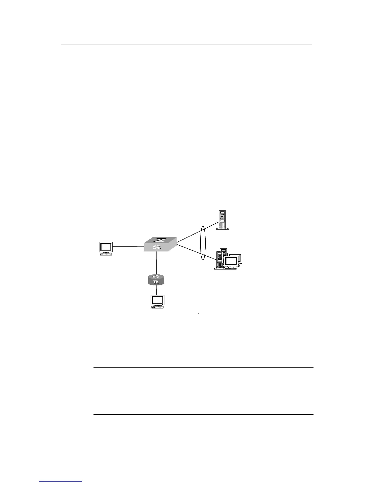
z User PC2 accesses the switch through the router. Configure Layer 3 Portal
authentication for the switch. After passing the Portal authentication, user PC2 can
access the exterior network.
II. Network diagram
Switch
Portal server
RADIUS
Vlan-interface 2
192.168.1.160/16
192.168.1.100/16
192.168.1.200/16
VLAN 2
User PC2
Gateway address :162.31.1.1
IP address :162.31.1.2/16
162.31.1.1/16
Ethernet 0/0
Ethernet0/6
Vlan-interface 100
162.21.1.1/16
Ethernet 1/0
162.21.1.2/16
User PC1
Switch
Portal server
RADIUS
Vlan-interface 2
192.168.1.160/16
192.168.1.100/16
192.168.1.200/16
VLAN 2
User PC2
Gateway address :162.31.1.1
IP address :162.31.1.2/16
162.31.1.1/16
Ethernet 0/0
Ethernet0/6
Vlan-interface 100
162.21.1.1/16
Ethernet 1/0
162.21.1.2/16
User PC1
Switch
Portal server
RADIUS authentication/accounting server
Vlan-interface 2
192.168.1.160/16
192.168.1.100/16
192.168.1.200/16
VLAN 2
User PC2
Gateway address :162.31.1.1
IP address :162.31.1.2/16
162.31.1.1/16
Ethernet 0/0
Ethernet0/6
Vlan-interface 100
162.21.1.1/16
Ethernet 1/0
162.21.1.2/16
User PC1
Switch
Portal server
RADIUS
Vlan-interface 2
192.168.1.160/16
192.168.1.100/16
192.168.1.200/16
VLAN 2
User PC2
Gateway address :162.31.1.1
IP address :162.31.1.2/16
162.31.1.1/16
Ethernet 0/0
Ethernet0/6
Vlan-interface 100
162.21.1.1/16
Ethernet 1/0
162.21.1.2/16
User PC1
Switch
Portal server
RADIUS
Vlan-interface 2
192.168.1.160/16
192.168.1.100/16
192.168.1.200/16
VLAN 2
User PC2
Gateway address :162.31.1.1
IP address :162.31.1.2/16
162.31.1.1/16
Ethernet 0/0
Ethernet0/6
Vlan-interface 100
162.21.1.1/16
Ethernet 1/0
162.21.1.2/16
User PC1
Switch
Portal server
RADIUS
Vlan-interface 2
192.168.1.160/16
192.168.1.100/16
192.168.1.200/16
VLAN 2
User PC2
Gateway address :162.31.1.1
IP address :162.31.1.2/16
162.31.1.1/16
Ethernet 0/0
Ethernet0/6
Vlan-interface 100
162.21.1.1/16
Ethernet 1/0
162.21.1.2/16
User PC1
Switch
Portal server
RADIUS
Vlan-interface 2
192.168.1.160/16
192.168.1.100/16
192.168.1.200/16
VLAN 2
User PC2
Gateway address :162.31.1.1
IP address :162.31.1.2/16
162.31.1.1/16
Ethernet 0/0
Ethernet0/6
Vlan-interface 100
162.21.1.1/16
Ethernet 1/0
162.21.1.2/16
User PC1
Switch
Portal server
RADIUS authentication/accounting server
Vlan-interface 2
192.168.1.160/16
192.168.1.100/16
192.168.1.200/16
VLAN 2
User PC2
Gateway address :162.31.1.1
IP address :162.31.1.2/16
162.31.1.1/16
Ethernet 0/0
Ethernet0/6
Vlan-interface 100
162.21.1.1/16
Ethernet 1/0
162.21.1.2/16
User PC1
Switch
Portal server
RADIUS authentication/accounting server
Vlan-interface 2
192.168.1.160/16
192.168.1.100/16
192.168.1.200/16
VLAN 2
User PC2
Gateway address :162.31.1.1
IP address :162.31.1.2/16
162.31.1.1/16
Ethernet 0/0
Ethernet0/6
Vlan-interface 100
162.21.1.1/16
Ethernet 1/0
162.21.1.2/16
User PC1
Figure 2-4 Network diagram for Layer 3 Portal authentication
III. Configuration procedure
Note:
The following describes the configurations of Layer 3 Portal authentication. For the
configurations of the RADIUS scheme, ISP domain and Portal server, refer to section
2.2.3 “Portal Direct Authentication Configuration Example”.
 Loading...


