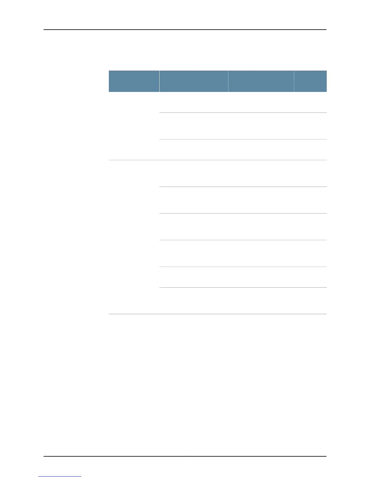
Table 28: M40 Router Chassis Component Alarm Conditions (continued)
Alarm
SeverityRemedyAlarm Condition
Chassis
Component
YellowInsert a power supply into
an empty slot.
A power supply was removed
from the chassis.
Power supplies
YellowReplace the failed power
supply or power entry
module.
A power supply temperature
sensor failed.
YellowReplace the failed power
supply fan.
A power supply fan failed.
RedReplace the failed power
supply or power entry
module.
A power supply has high
temperature.
RedReplace the failed power
supply or power entry
module.
A 5V power supply has failed.
RedReplace the failed power
supply or power entry
module.
A 3.3V power supply failed.
RedReplace the failed power
supply or power entry
module.
A 2.5V power supply failed.
RedCheck the power supply
input connection.
A power supply input failed.
RedReplace the failed power
supply or power entry
module.
A power supply has failed.
Copyright © 2012, Juniper Networks, Inc.78
M Series and T Series Routers Monitoring and Troubleshooting Guide