4-39
4-6 Wiring Regenerative Resistor
SIGNALS AND WIRING
- SV Series User’s Manual -
■
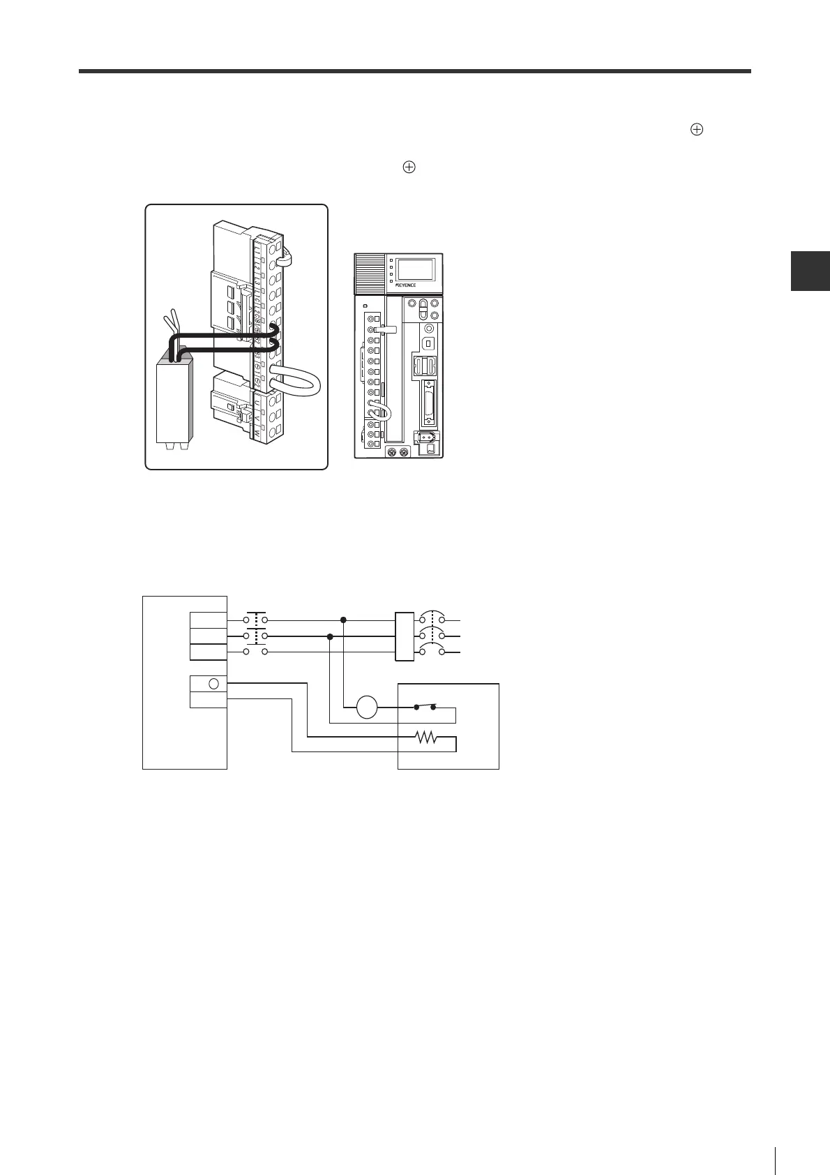
Connecting regenerative resistor with SV-075
2, SV-100
2, SV-150
2, SV-200
2, SV-300
2, SV-500
2
Remove the wires connecting B2 and B3 terminals, and then wire the regenerative resistor to B1/ and B2
terminals.
The regenerative resistor can be connected to B1/ and B2 terminals independent on the polarity.
Be sure to remove the wires connecting B2 and B3 terminals and then wire.
■ Wiring example of thermostat
When regenerative resistors are used, be sure to use thermostat, and make the sequence control program for
stopping the servo motor when thermostat output is enabled.
External regenerative resistors
Servo amplifier
External regenerative resistor (OP-84399/OP-87073)
NFB
Thermostat
FIL
R
S
T
L2
B1/ +
L3
B2
MC
L1
White
White
Black
Black
MC
 Loading...